


Elmo PSS User Guide Product Description
MAN-PSSUG (Ver. 3.01)
2-2
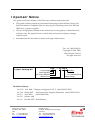
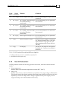
Term.
Block
32-pin
connector
Function Comment
1 12 - 22 (J2) Power output return (PR) For DIN mounting, all six pins must be
connected.
2 24 - 32 (J1) AC-1 supply input (through
an isolated/floating
transformer)
For DIN mounting, all five pins must
be connected.
3 14 - 22 (J1) AC-2 supply input (through
an isolated/floating
transformer)
For DIN mounting, all five pins must
be connected.
4 4 - 12 (J1) AC-3 supply input (through
an isolated/floating
transformer)
For DIN mounting, all five pins must
be connected.
5 24 - 32 (J2) Positive power output (VP+) For DIN mounting, all five pins must
be connected.
6* 4 (J2) Inhibit indication output Whenever power supply is inhibited
(e.g. during thermal/duty cycle), this
open collector output goes into low
state (maximum sink current: 10 mA,
30 VDC).
7** 8 (J2) Fan supply 24 VDC/0.5 A output for an external
brushless fan. Common is available in
terminal 1
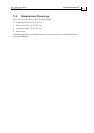
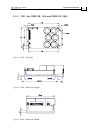
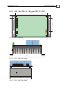
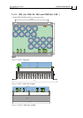
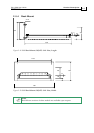
Table 2-2: PSS Terminal Description: 6U Power Supplies
* Inhibit indication return is available in terminal 1.
** Available for 60A types only.
2.2 Fault Protection
All PSS products include the following protective functions, which activate the internal
inhibit:
Over-temperature
Inhibits shunt when heatsink temperature exceeds 90 °C (194 °F).
Duty cycle
Inhibits shunt whenever On and Off time exceeds 5% to 10% (depending on PSS model).
This feature protects the shunt regulator when high-inertia loads are driven by the servo
amplifier(s) or when too high an AC voltage is applied to the power supply (i.e. DC
output is already above the threshold of the shunt).