


2
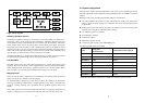
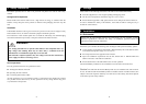
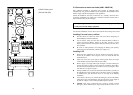
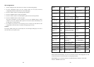
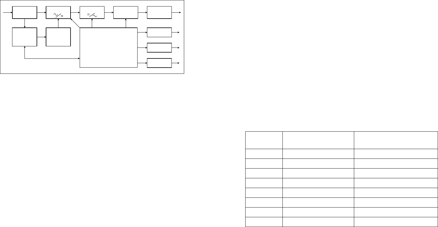
Fig.1. Block diagram
Efficiency Optimizer function
The Efficiency Optimizer function is a new feature for the UPS adding cost effectiveness,
minimizing power loss and reducing power consumption. Alternating between bypass and
on-line modes is achieved automatically and in accordance with the conditions of the utility
power. On-line mode may be used during times of intermittent power supply, and bypass
mode when power flows smoothly in order to obtain greatest efficiency. Irregularities can be
detected in less than a second, and on-line mode reactivated immediately. Switching back to
online mode occurs when input voltage is outside ±10% or nominal (±15% selectable), when
input frequency is outside of ±3Hz or when no input line is available.
Although high efficiency is standard, the default operation is in on-line mode. Bypass can be
activated in the LCD panel, though on-line can be run permanently if preferred.
Free Run Mode
The UPS operates in free run mode when input frequency is outside of the selected input
frequency range. Free run mode is when output frequency does not match input frequency.
When starting the UPS, the frequency regulation detected is 50 or 60 Hz ±0.25Hz. Please
refer to chapter 7.2 if you want bypass available while running in free run mode.
Diagnostic tests
When you start the UPS, a diagnostic test is automatically executed that checks electronics,
battery, and reports any problems on the LCD display.
An advanced battery management system always monitors the conditions of the batteries
sends any forewarnings if replacement is needed. Otherwise every 30 days of normal mode
operation, a battery discharge test is performed and any problems reported on the LCD
display.
Except during the first 24 hours after startup while the UPS is in charging mode (please see
chapter 7.2), diagnostic tests can be performed manually from the front panel at any time.
Filter
By-pass
switch
Filter
Charger &
Battery
switch
Battery
Monitoring
panel
RS232 or
USB
Slot
Control
&
Monitoring
PFC&Booster
Inverter
3
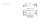
2.2 System configuration
The UPS device and the internal backup battery make up the system. Depending on the site
and load requirements of the installation, certain additional options are available as a tailored
solution.
Planning a UPS system, the following should be taken into consideration:
z The total demand of the protected system shall dictate the output power rating (VA).
Allow a margin for future expansion or calculation inaccuracies from measuring power
requirements.
z Backup time needed will indicate the battery size needed. If load is less than the UPS
nominal power rating then actual backup time is longer.
z The following options are available:
z External Battery Cabinets
z Transformer cabinets
z Maintenance bypass switches
z Connectivity options (relay card, SNMP/WEB card)
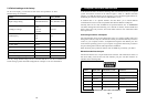
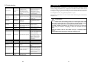
The following UPS models are available
Model
Backup time
Internal batteries
Recharge time to 90% capacity
UPS 4000VA 4min 4 hours
UPS 5000VA 4min 4 hours
UPS 6000VA 7min 4 hours
UPS 8000VA 4min 4 hours
UPS 10000VA 4min 4 hours
UPS 12000VA 8min 4 hours
UPS 15000VA 6min 4 hours
UPS 20000VA 4min 4 hours
Additional External Battery Cabinets are available if more back-up time is needed.