Design Guide & Applications Manual
For VI-200 and VI-J00 Family DC-DC Converters and Configurable Power Supplies
vicorpower.com 800-735-6200 Applications Engineering 1-800-927-9474 Rev. 2.1
Page 24 of 88
C
FET
C
Rectifier
I
CM
C
FET
C
Rectifier
C
External
C
External
I
CM
Primary Secondary
V
p
V
p
V
p
Baseplate
I
DM
Ycaps Ycaps
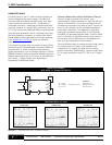
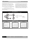
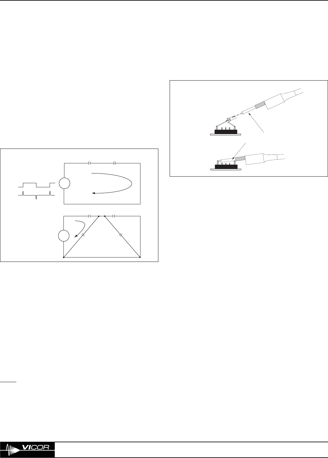
Figure 9–8 — Noise coupling model
9. EMC Considerations
To Scope
Ground Ring on Probe
To Scope
or
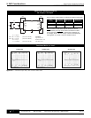
Insert probe into female receptacle
(Vicor P/N 06207) for proper output
differential noise measurement technique
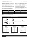
Figure 9–9 — Output ripple measurement technique
The dv/dt of the switch (FET) is a noise generator. This
FET is mounted on a two layer insulating and shielding
assembly which is attached to the baseplate. Since ceramic
is a dielectric, there is capacitance from the FET to the
baseplate. (Figure 9–7) The output rectifiers are also tied
to the baseplate with ceramic insulators, adding additional
capacitance. The dv/dt of the FET is differentiated by these
two series capacitors, resulting in a spike of noise current
at 50 – 70 MHz that flows from primary to secondary.
(Figure 9–8) This noise current is common-mode as opposed
to differential, and therefore should not affect the operation
of the system. It should be noted, however, that oscilloscopes
have a finite ability to reject common-mode signals, and
these signals can be abnormally emphasized by the use of
long ground leads on the scope probe.
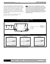
MEASURING OUTPUT NOISE
Long ground leads adversely impact the common-mode
rejection capability of oscilloscopes because the ground
lead has inductance not present on the signal lead. These
differing impedances take common-mode signals and
convert them to differential signals that show up on the
trace. To check for common-mode noise, place the
oscilloscope probe on the ground lead connection of the
probe while the ground lead is tied to output return.
(Figure 9–9) If the noise is common-mode, there will still
be “noise” observed at the same test point.
NOTE
: The output return must be at the same relative
potential as the earth ground of the oscilloscope or
damaging current may flow through the oscilloscope
ground lead.
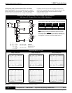
Capacitors are required from the +/–IN to the baseplate
thereby shunting common-mode current, thus reducing
noise current on the input power lines. The capacitor must
have very short leads since the frequency is high. It must
also be a good capacitor (i.e., ceramic or other material
that has a low ESR / ESL). This type of capacitor is most
important on high input voltage units since the “dv”
is larger, but is required for all units. For off-line
applications this capacitor must have the appropriate
safety agency approvals.
A capacitor from +/–Vout to the baseplate, is required
since the output rectifier has a changing voltage on it,
and, like the FET, can generate common-mode noise.
This capacitor is similarly recommended for high output
voltage units (48 V).
Common-mode noise is not differential with respect to
the output. It does, however, flow in both input and
output leads of the power supply and is a noise parameter
that is measured by the FCC or VDE. It can cause power
systems to fail radiated emission tests, so it must be dealt
with. Bypass capacitors to the baseplate with a common-
mode filter on the input of the module or the main input
of the power supply is required.
The common-mode filter is typically placed on the input as
opposed to the output. Theoretically, since this current
flows from primary to secondary, the choke could be
placed in either the input or the output, but is preferably
placed in the input leads for the following reasons:
1) input currents are smaller since the input voltage is
usually higher;
2) line regulation of the module can correct for voltage
drops across the choke; and
3) if the choke is on the output and the senses are
connected to the other side of it, the stability of the
loop may be impacted.
Differential output noise is the AC component of the
output voltage that is not common to both outputs. The
noise is comprised of both low frequency, line-related
noise (typically 120 Hz) and high frequency switching noise.


