3
SETTING UP THE ATS ANNUNCIATORS
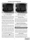
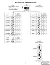
Catalog 214A400, 214A404 Master ATS Annunciators Catalog 214A401 Slave ATS Annunciator
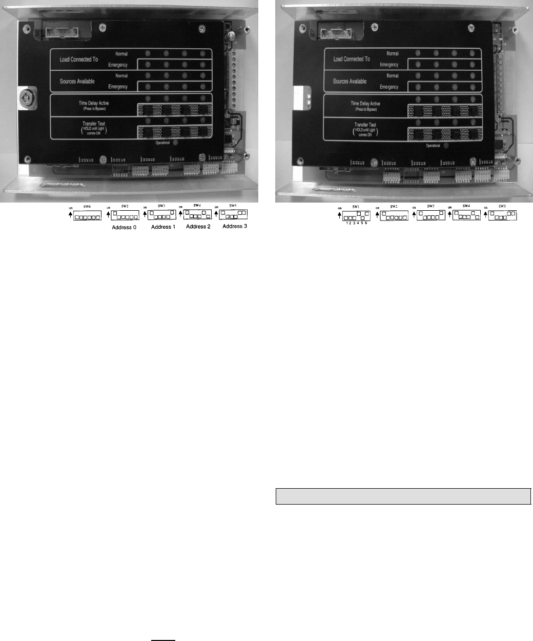
Master ATS Annunciator factory default settings Slave ATS Annunciator factory default settings
Figure 5. DIP switches in Master. Figure 6. DIP switches in Slave.
Before applying power to the ATS Annunciators, the
DIP switches must be set to select the number of Masters
and Slaves, Master Address, an d th e addresses of eac h
automatic transfer switch connected. Refer to Figures 5
and 6 for the location of DIP switches. See Charts 1, 2,
3, and 4 for position of actuators for each setting.
Set Number of Masters and Master Address
ASCOBUS I communication protocol supports
single– and multi–master, daisy chain, and star confi-
gurations. Group 7/7A and 5 Controllers can be
connected on the same network. In this case the Group
5 menu item selecting the serial communication baud
rate must be set to x9600.
When more than one Master is being used, one
Master must be selected as the Lead Master. Then the
L ead Master must be told how many other masters
there are. DIP switch S6 shown in Figure 5 on the
Master ATS Annunciator selects how many Masters
are being used (up to seven) and their addresses.
Actuators 1 through 3 set the number of Masters
(Chart 1 ) and actuators 4 through 6 set their addresses
(Chart 2). For example, if only one Master is used,
actuators 1 through 6 should be down (off). If more
than one Master is used, select one as a Lead Master
and s et all other Masters to different address.
To select the ASCOBUS II communication proto-
col, the DIP switches S6 actuators 1,2,3 must be set to
ON position (ATS Annunciator must
be deenergized).
With ASCOBUS II protocol selected, Group 1 and 5
Controllers can be connected on the same network and
the only configuration supported is the daisy chain
configuration with single master annunciator and up to
2 slaves (see drawing 401900). In this case the Group
5 Controller menu selection for the serial communica-
tion baud rate must be set to 9600.
Set Number of Slaves
DIP switch S1 showninFigure6,(ontheleftsideofeach
Slave) selects t he number of the S lave (either 1 or 2).
Refer to Chart 3. F or example, if only one Slave is used,
depress the actuators shown in the top figure (setting for
Slave 1). If two Slaves are used, set one to the setting for
Slave 1 an d on the other Slave d ep ress t h e actuato rs
showninthelowerfigure(settingforSlave2).
Setting the ATS Address Number
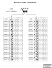
DIP switches S2, S3, S4, and S5 on t he ATS Master
(Figu re 5) and Slave A n n u n c iat o rs (Fig u re 6) are used to
set the unique address number for each ATS. Up to 32
ATSs can be acc ommo d at ed on a syst em utilizing three
Masters and five Slaves.
Actuator 1 must be on ( up) for each address being used.
Refer to Chart 4 for selecting a unique address number
foreachATS.OneDIPswitchisusedforeachATS.
For example, ATS 1 would use address 00 so set DIP
switch S2 (on the Master) with actuators 2---6 down
(off).ATS2woulduseaddress01sosetDIPswitchS3
(on the Master) with actuator 6 up (on). Remember to
move actuator 1 up (on) for each DIP switch being
used! Refer to Table D at the back of this manual.
ATS Label Holder
The ATS Annunciator is labeled for ATS1, ATS2,
ATS3, and ATS4. Included with each ATS Annunciator
is an adhesive–backed label holder with labels for
AT S 5 --- 1 2 and some blank labels. Label each ATS
Annunciator with the ATS numbers that are addressed
in it. Fill in Table D at the back of this manual.


