


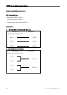
Series HMI Connection Manual
Definition of PLC Read/Write Address
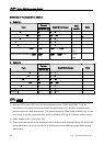
a. Registers
42 V1.01 Revision November, 2011
Format
Type
Word No. (n)
Read/Write Range
Data
Length
Note
Data Word D Dn D0 – D7999 Word
Special Data Word SD SDn SD0 – SD255 Word 3
Data Word Z Zn Z0 – Z15 Word
Timer T Tn T0 – T255 Word
Counter C Cn C0 – C199 Word
Double word Counter CDW CDWn CDW200 – CDW255 Double
Word
Double word Data Word DDW DDWn DDW0 – DDW7998 Double
Word
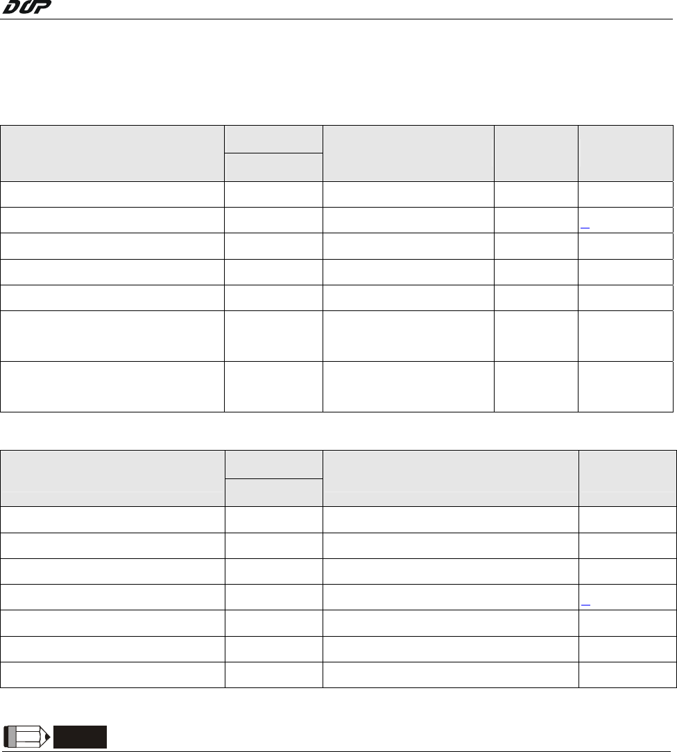
b. Contacts
Format
Type
Bit No. (b)
Read/Write Range Note
External Output Relay Y Yb Y0 – Y377 Octal
External Input Relay X Xb X0 – X377 Octal
Internal Relay M Mb M0 – M1999
Special Internal Relay SM SMb SM0 – SM255 3
Status Relay S Sb S0 – S991
Timer T Tb T0 – T255
Counter C Cb C0 – C255
NOTE
1) Emerson EC20 series PLC has two communication ports, COM0 and COM1. They are
provided for the communication protocol for connecting to PC, Modbus communication
protocol and user-defined protocol. The default setting is COM0 to be enabled only, so the
user needs to set the communication mode as Modbus RTU via PC software before using it.
2) COM1 supports RS-232 and RS-485.
3) Please note that not all of the addresses can be written when reading SM and SD device. We
recommend the user not to set all of the addresses as write address except when setting
parameters.