Wiring Considerations
22
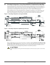
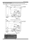
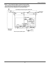
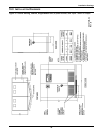
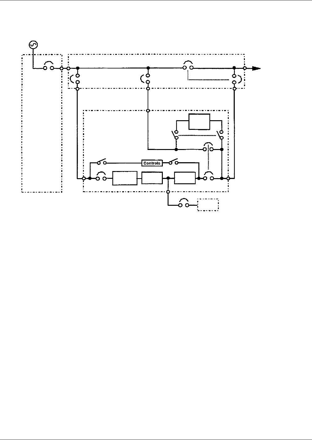
Figure 9 Power single-line diagram, optional 12-pulse rectifier*
Four-breaker maintenance bypass switchboard
FB
Critical load
AC output
Battery
Control power
MBD
BIB
MBB
MIB
UPS module
Static
switch
disconnect
Static
bypass
switch
Bypass CB
Output CB
Main input
switchgear
RIB
*Rectifier
isolation
Xfmr
Inverter
Input
CB
Rectifier/
charger
*Part of 12-pulse rectifier option
* This configuration is for illustrative purposes only. It represents only a
sample of the possible configurations. Refer to the submittals supplied
with your order for more information or for order-specific details.


