Installation
2
1.1.2 Connecting the Dual Unit Controller to the InteleCool
1. Install and level the Dual Unit Control.Leveling is not critical because the electronic thermostat
does not contain mercury-filled limit switches.
2. Wire the InteleCool units to the Dual Unit Control using industry-standard thermostat cable.
Each InteleCool will need at least 4 conductor, 20 gauge, Class 2 copper wire for distances up to
50 feet (15.2m). Use 18 gauge, Class 2 copper wire for distances between 50 and 75 feet (15.2 -
22.9m).
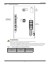
3. Wire the Dual Unit Control per the diagram on the inside cover of the Dual Unit Control. The
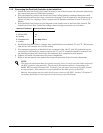
InteleCool to Dual Unit Control low voltage control wiring connections are as follows:
4. Each InteleCool MUST have a jumper wire installed between terminals "G" and "Y". This assures
that the fan will energize on a call for cooling.
5. For continuous operation of InteleCool unit evaporator fans, the "G" and "R" terminals may be
connected. In this mode the jumper between the "G" and "Y" terminals should be removed, and
the lead/lag function will control only the condenser fans, compressors, and heaters.
6. Tighten and check all connections for correct installation.
7. Refer to the thermostat user manual for setup and operation of the electronic thermostat.
InteleCool Terminals Dual Unit Control Terminals
R & 1 - 24 VAC R
2 - 24 VAC RTN 1/2
W - Heating W
G - Evaporator Fan See Step 4 Below
Y - Cooling Y
NOTE
The electronic thermostat does not contain mercury, but it is not for use with older versions of
the DUC printed wiring assembly. The electronic thermostat requires a connection to the
24VAC RTN terminal (Connector P1, Terminal 7) on the newer versions of the DUC printed
wiring assembly. This connection is not available on the older version of the DUC.
Mercury thermostats may be used with the newer version of the DUC, but the P1 Terminal 7
connection noted above is not required for the mercury-style thermostat.


