6
Liebert STS2 Communication
and Product Options
Liebert STS2 has a wide choice of monitoring and
communications options to keep you connected to your
critical power protection system.
R
S-232 Terminal Port
— S
tandard on all units, this port
is primarily used as an alternate user interface to
configure, control, and diagnose the system.
Input Contact Isolator (ICI) Board — Customizable
input relays allow alarms from other devices to be
displayed on Liebert STS2 display. Provides an interface
for up to eight user inputs. External messages and alarms
can be routed to the unit, via the ICI.
Programmable Relay Board (PRB) — Programmable
output relays for custom customer alarms and
connections. Up to two PRBs can be installed in the
Liebert STS2 to route system events to external devices.
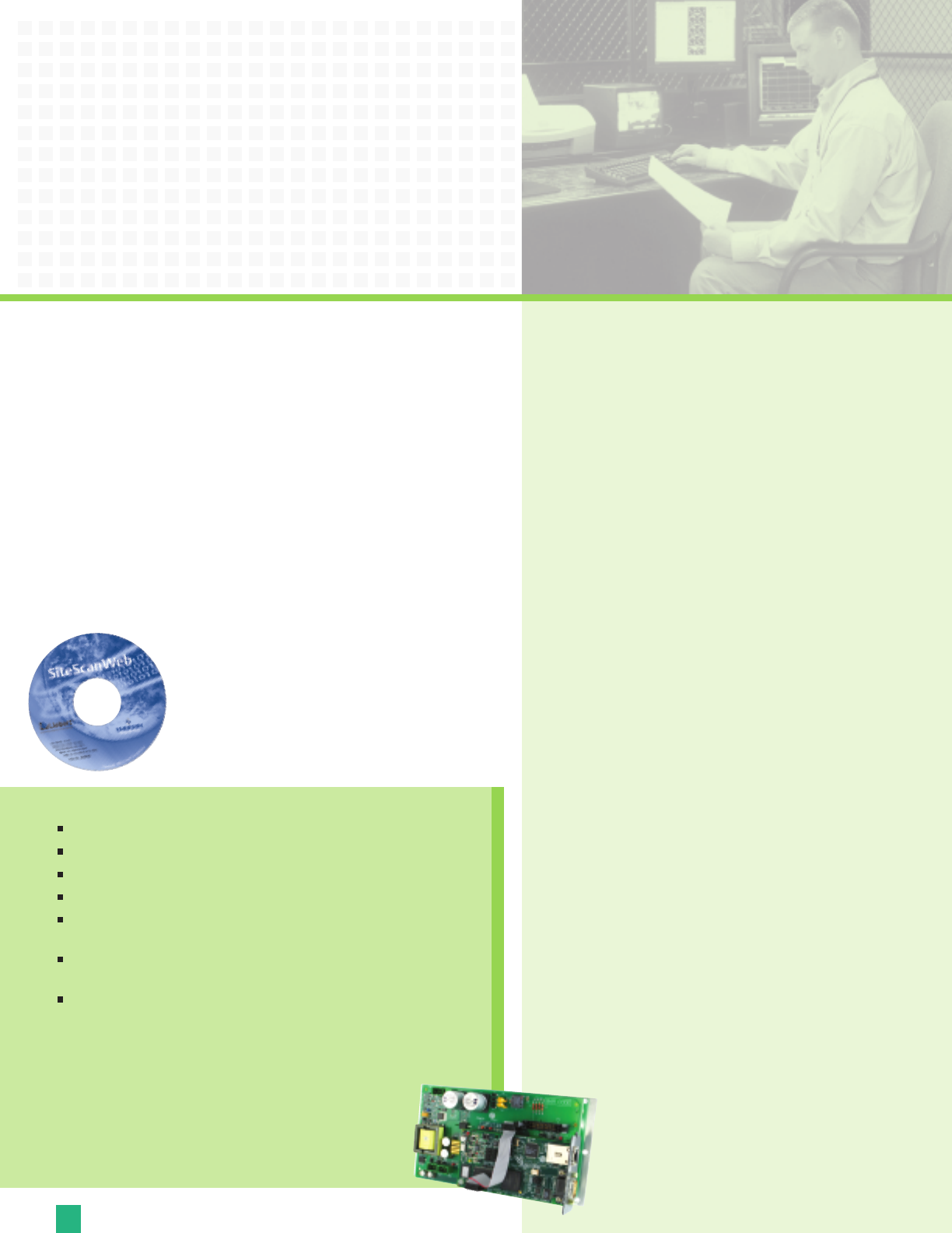
Comms Board — Includes a terminal block to provide a
DTE connection to an external modem. This board also
provides a direct connection to a Liebert SiteScan
®
Web
system, via an RS-422. SiteLink-12 or SiteLink-4 is
required for SiteScan to communicate with the
Liebert STS2.
Options and Accessories
Seismic Anchors
— To ensure stability for the unit in the event
o
f seismic activity, anchors are available for securing the unit to
a concrete floor to meet seismic Zone 4 requirements.
Seismic Floor Stand — Designed to level the unit and provide
bottom cabling access without relying upon a raised floor for
support. Available in 18, 24, 30, 36 inch heights.
Distribution Cabinet (Up to 600A) — An output distribution
cabinet mounts on the side of the STS2. It is a full height
section with hinged doors to allow for easy access. The cabinet
contains one vertically mounted I-line panelboard for load
distribution. The panelboard is totally enclosed with an accent
cover that provides access without exposing other portions of
the unit. The panelboard provides space for 100A through 250A
three-pole branch circuit breakers. It also includes a separate
isolated neutral bus bar and safety-ground bus bar for the
neutral and safety-ground connections.
Redundant Output Breaker — An output plug-in, non-
automatic circuit breaker provides redundancy in the output
power path. The breaker is connected in parallel with the
output plug-in non-automatic circuit breaker.
Input Junction Boxes and Cable (Up to 600A) — The input
junction box option is available to simplify input connections to
the STS2. Two input junction boxes and the associated flexible
10-foot long input cables are provided with this option.
A
vailable with bottom cable entrance only, typically when the
unit is located on a raised floor.
R
e
m
o
te Source Selection
— An o
p
ti
on
al Remote Source
Se
lection board may be installed in your STS2. This option
allows you choose the preferred input source from a remote
location. Terminal connections enable you to remotely select a
p
r
e
f
e
r
r
ed source in the same process as the local source
tr
ansfer selection.
Key Lockout Switch — The key lockout switch activates a
software lockout of the touch-screen display to prevent manual
transfers and configuration changes. When locked out, the
touch-screen becomes a read only display. A key is needed to
pe
rform manual transfers or change settings.
Liebert IntelliSlot
™
485 Web Card ADPT
Allo
ws s
ystems to be viewed from the network using a web browser.
D
e
li
v
e
rs SNMP, Telnet and web management.
Pr
o
vi
de
s s
ec
urity using HTTPS message encryption.
Supports 10 and 100 MBit Ethernet for legacy and modern networks.
Provides compatibility with
Liebert MultiLink shutdown software,
t
o p
r
e
vent data loss and ensure data availability.
Su
p
por
ts
L
i
e
be
r
t SiteScan WEB
e
n
t
e
r
prise monitoring software, to provide
trending for proactive analysis and maintenance to ensure facility uptime.
Interfaces to
Liebert Nform alarm notification software, to facilitate
quick corrective action.
Li
e
be
r
t In
telliSlot 485 Web Card ADPT provides connectivity to any
TCP/IP-based Ethernet network to allow the device to communicate with
network management systems (NMS) via SNMP. Events can be
tr
ansmitted to the NMS to provide remote status monitoring,
plus fault and alarm detection. The card includes an RJ-45 port for
an Ethe
r
net connection, via Category 5 cable. The card can also
in
t
egr
a
t
e the s
y
s
tem with an existing Building Management
System (BMS) or out-of-band monitoring, using Modbus.


