


2
© 2007 Liebert Corporation
All rights reserved throughout the world. Specifications subject
to change without notice.
® Liebert and the Liebert logo are registered trademarks of
Liebert Corporation. All names referred to are trademarks or
registered trademarks of their respective owners.
SL-29105_REV02_10-07
Liebert Corporation
1050 Dearborn Drive
P.O. Box 29186
Columbus, OH 43229
Telephone: 1-800-877-9222
Facsimile: 1-614-841-6022
www.liebert.com
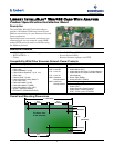
Customer Wiring
Specifications
Wiring Specifications
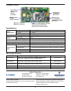
Power
Requirements
AC Inputs 18 - 24 VAC; 50/60 Hz
DC Inputs 12 - 36VDC
Power Consumption 6VA maximum
Dimensions - W x D x H: in. (mm) 7 x 4 x 1.5 (178 x 102 x 38)
Weight
Net - oz. (kg) 7 (0.2)
Shipping - lb. (kg) 1.3 (0.6)
Ambient Operating Environment, °F (°C) 32 to 104 (0 to 40); 10% to 90% RH (non-condensing)
Ambient Storage Temperature, °F (°C) -4 to 140 (-20 to 60)
Protection SELV Isolated User Connections, Watchdog Timer Circuitry
Communication
Ports
Service Terminal (RS-232) DB9F, DTE
Unit Input
Communications
TB1, 2-Position Terminal Block
P1, 20-PIN Vertical Header with Ejection Latches (for some UPS models)
Modbus (RS-485) TB2, 2-Position Terminal Block
Ethernet Communications RJ45
Connection Supported Wire Types Maximum Wire Length
TB1 (RS-422)
18-22 AWG Stranded & Shielded; 18 AWG* recommended
Non Plenum - Belden 9461; Plenum - Belden 88761
1000 ft. (300m)
TB2 (RS-485)
18-22 AWG Stranded & Shielded; 18 AWG* recommended
Non Plenum - Belden 9461; Plenum - Belden 88761
3000 ft. (915m)
TB3 (Power Input)
18-22 AWG Stranded & Shielded; 18 AWG* recommended
Non Plenum - Belden 8770; Plenum - Belden 88770
20 ft. (6m)
DB9F Connector DTE Null Modem Cable 50 ft. (15m)
RJ45 Connector Standard Category 5 Cable 328 ft. (100m)
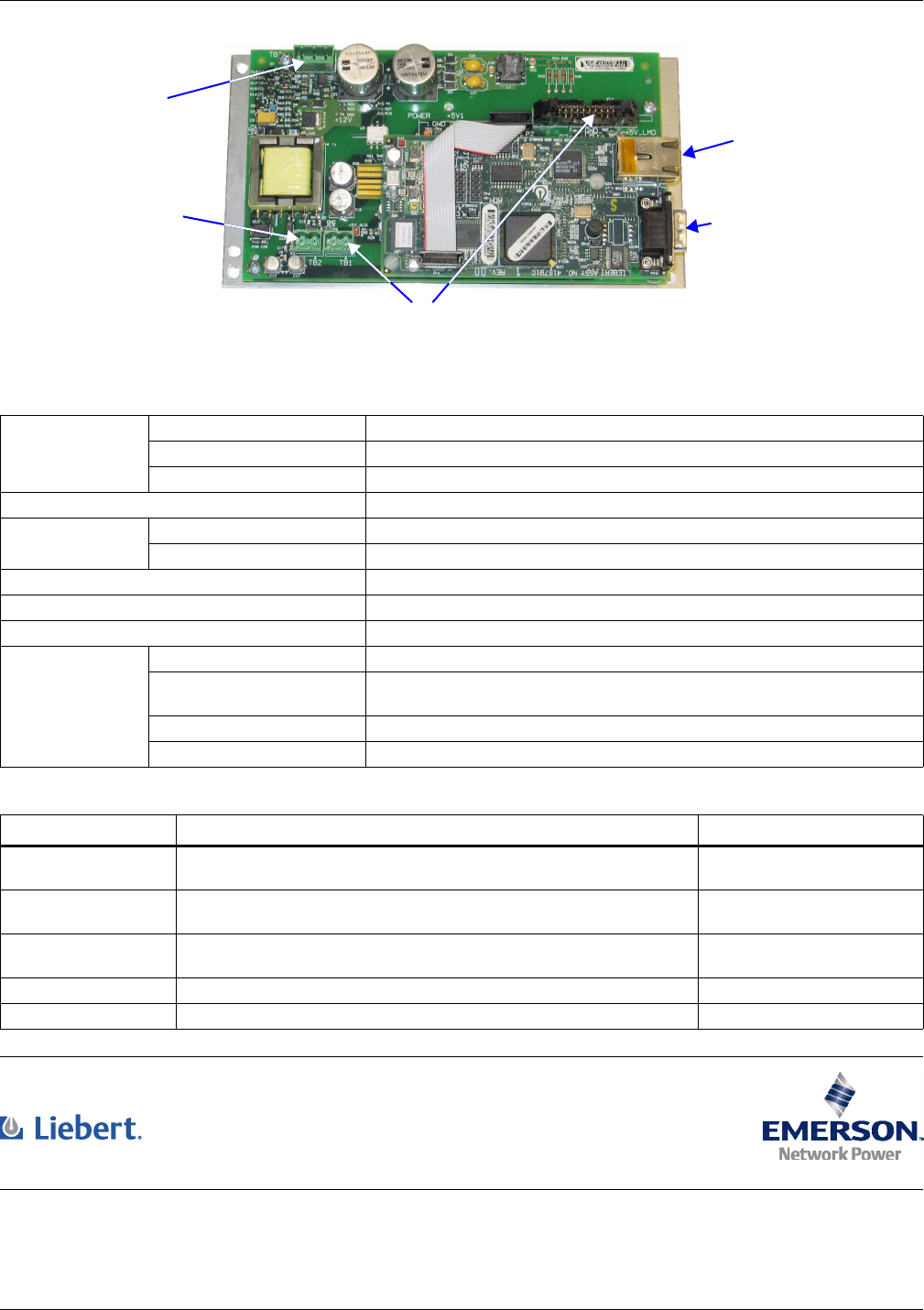
Input power
(input to TB3)
Pin 1(+)
Pin 2(-)
Pin 3 (NC)
Network port
for NMS and
Web access
DTE serial port
for configuration
(requires null-modem
connection)
IGMnet or Liebert SiteScan
®
Comms
from unit (input to TB1 or P1)
Refer to user manual for details
Modbus output
for BMS
(output from TB2)
TB1: Pin 1 (+), Pin 2 (-)
TB2: Pin 1 (+), Pin 2 (-)