


8 9
CO H2S
02 LEL
ATX612
VER 1.0
5
O 0
21.0 0
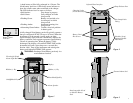
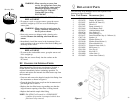
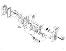
The remote sample tube should be connected to the barbed
inlet fitting on the bottom of the ATX612 (See Figure 3).
NOTE: When drawing a remote sample, allow 2 seconds
per foot (0.3 meter) of tubing length in addition to
the normal sensor response time before observing
the instrument readings.
The instrument is protected from drawing liquid and dust
into the pump and sensors by an internal 1.2 micron dust
filter/water stop.
4.5 OPERATING MODES
The ATX612 offers different operating modes to access
various instrument features. To scroll through the
operating modes, press and release the MODE switch. The
operating modes will appear in the following order:
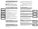
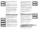
4.5.1 READING
This is the normal operating mode. The current reading of
all sensors is displayed along with the graphical battery
charge indicator.
4.5.2 SENSOR CONFIGURATION
This mode will display the type of sensor in the position in
which it is installed in the instrument.
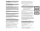
4.5.3 PPM HYDROCARBON
This mode displays the level of total hydrocarbons with 50
PPM resolution. The PPM reading may be rezeroed at
anytime by pressing the enter (E) key. The display will
return to the normal operating mode if the gas
concentration exceeds the LEL alarm level set in the
instrument.
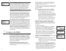
4.5.4 ZERO
This mode allows the user to zero the instrument and
calibrate all installed sensors. Refer to Section 5,
Calibrating the ATX612, for instruction on the use of the
automatic zero and calibration functions.
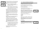
4.5.5 PEAK
This mode will display the highest level of toxic and
combustible gas and the lowest level of oxygen measured
since the peak readings were last cleared.
HOLD
RELEASE
4.1.1 ALKALINE BATTERY OPTION
The ATX612 is available with an optional alkaline battery
pack which will typically operate continuously for up to
20 hours using 6 C-cell batteries.
WARNING:
Replace alkaline battery cells only in a
non-hazardous location. Use only Duracell, Energizer,
Procell, Panasonic, Varta or Kodak C-cell alkaline batteries. Use
of another battery type may present a risk of fire or explosion
and will violate the intrinsic safety certification of the ATX612.
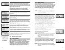
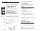
4.2 TURNING THE ATX612 ON AND OFF
• Press and hold the ON/OFF/MODE switch. The display
will read HOLD and the instrument sounds a short beep
once a second.
• Continue holding the MODE switch for 5 beeps until the
RELEASE screen appears. (Stop here if turning the
instrument off.)
• After the instrument is turned ON, the following startup
screens will be displayed:
SOFTWARE VERSION: The version of the operating
software installed in the instrument is displayed.
SENSOR CONFIGURATION. The type of sensors
installed in the instrument will be displayed.
WARM-UP TIMER. The display will indicate the
number of seconds remaining until the instrument begins
normal operation.
After the warm-up sequence has been completed, the
ATX612 will enter the normal operating mode and will
be continuously monitoring all calibrated sensors.
4.3 DISPLAY BACKLIGHT
The display backlight is automatically switched on when
the ATX612 is in an alarm condition. To manually activate
the backlight, press and release the (E) key. The backlight
will remain on for approximately 15 seconds.
4.4 INTERNAL SAMPLING PUMP
The ATX612 is equipped with a built-in pump for remote
gas sampling. The sampling pump will draw a constant flow
sample from up to 100 feet (30 meters) using 1/8 inch (3
mm) diameter tubing.
CO H2S
02 LEL
PPM EXP
0
ZERO
PRESS
65P 8
19.3K 12
!