


GSM/GPRS Spider SA User Manual
GSM0000PB001MAN 11 Version 1.07 - 02/14/05
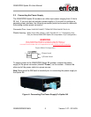
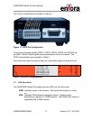
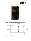
The I/O pin configuration is provided in Figure 11.
Figure 11: GPIO Pin Configuration
Five general-purpose signals (GPIO1, GPIO3, GPIO5, GPIO6, and GPIO7) are
provided. Each of these signals may be selected as inputs or outputs. The
GPIO characteristics are provided in Table 3.
One audio input and one audio output line is provided along with a ground line.
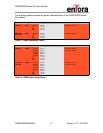
I/O Lines
Parameter/Conditions MIN TYP MAX UNIT
V
IL
Input Voltage – Low
-0.5 0.9 Vdc
V
IH
Input Voltage – High
2.0 3.4 Vdc
V
OL
Output Voltage – Low
0.64 Vdc
V
OH
Output Voltage – High
2.4 3.0 Vdc
I
IL
/ I
IH
Input Leakage Current
-1 1
µ
µµ
µ
A
I
OL
/ I
OH
Rated Output Current
2 mA
Table 3: SA GPIO Characteristics
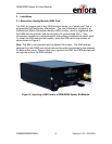
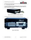
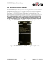
3.7 LED Functions
The GSM/GPRS Spider SA modem has two LED’s on the front panel.
PWR: Indicates power to the modem. Solid when the modem is turned
on.
REG: Indicates GSM network registration status. Flashing when
attempting to register on a GSM network. Solid when the modem is
registered with a GSM network.