


Table Of Contents
1 Introduction...........................................................................................................................1
1.1 About the GSM/GPRS MT-GL..............................................................................................1
1.2 About This Manual................................................................................................................1
1.3 Contents of Basic Package ..................................................................................................1
1.4 Available Accessories........................................................................................................... 1
1.5 System Requirements ..........................................................................................................1
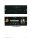
1.6 MT-GL Front and Back View ................................................................................................ 2
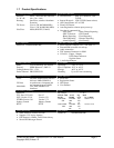
1.7 Product Specifications.......................................................................................................... 3
2 Installation.............................................................................................................................4
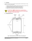
2.1 Mounting Dimensions........................................................................................................... 4
2.2 Installing Cables ................................................................................................................... 7
2.2.1 12 pin Connector............................................................................................................... 8
2.2.2 MT-GL Serial Adapter (Optional)......................................................................................9
2.3 Installing Subscriber Identity Module (SIM) Card...............................................................12
2.4 Audio In/Audio Out..............................................................................................................13
2.5 Connecting GSM/GPRS modem Antenna..........................................................................14
2.6 Connecting GPS Antenna ..................................................................................................15
2.7 Connecting the Power Source............................................................................................16
2.8 LED Operation....................................................................................................................17
3 Additional Software Features .............................................................................................18
4 Appendix 1 – Cable Wiring Diagrams.................................................................................20
Table of Figures
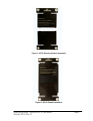
Figure 1 - Enfora MT-GL Front View...................................................................................................... 2
Figure 2 - Enfora MT-GL Back View.......................................................................................................2
Figure 3 - Mounting dimensions of a MT-GL (Shown with mounting plate)........................................... 4
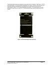
Figure 4 - MT-GL Mounting Bracket (attached)......................................................................................5
Figure 5 - MT-GL Mounting Bracket (separated) ...................................................................................6
Figure 6 - MT-GL Bracket Installation.....................................................................................................6
Figure 7 - MT-GL Bracket Installation.....................................................................................................7
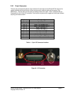
Figure 8 - I/O Connector......................................................................................................................... 8
Figure 9 - 12-Pin Connection..................................................................................................................9
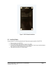
Figure 10 - Inserting a SIM...................................................................................................................12
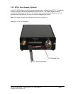
Figure 11 - GSM/GPRS Antenna Connection......................................................................................14
Figure 12 - GPS Antenna Connection.................................................................................................. 15
Figure 13 – Wiring for Power Only ....................................................................................................... 20
Figure 14 – Wire for Programming Cable............................................................................................. 20
Tables
Table 1 - 12 pin I/O Connector Interface................................................................................................8
Table 2 - Audio Settings .......................................................................................................................13
Table 3 - GSM Operating Power.......................................................................................................... 16
Table 4 - GPRS Operating Power........................................................................................................16