


GSM/GPRS Spider SA User Manual
GSM0000PB001MAN 5 Version 1.07 - 02/14/05
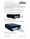
3.2 Connecting the Power Supply
The GSM/GPRS Spider SA modem can utilize input power ranging from 5 Vdc to
30 Vdc. If your unit did not include a power supply or if you wish to configure a
separate power interface, the following connector parts can be used to mate with
the existing modem power connector:
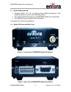
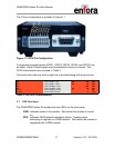
Connector Pins -
Molex 39-00-0207 MINIFIT TERM CRP FEM CHN BS TIN 18-24
Plastic Housing -
Molex 39-01-2020 4.20mm (.165") Pitch Mini-Fit, Jr.™ Receptacle, Dual
Row (the Enfora GSM/GPRS Spider SA incorporates a 2-pin configuration)
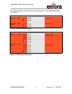
WARNING:
When assembling the Molex connector, plug the Positive (+)
power lead in the bottom of the Molex connector. Improper
connections will render the unit inoperable and will void the product warranty.
Proper Molex Configuration
(- )Power Lead
(+)Power Lead
TM
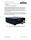
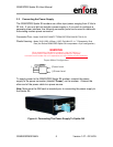
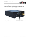
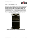
To supply power to the GSM/GPRS Spider SA modem, connect the power
supply to the power connector (labeled “Power”) on the modem. Connect the
other end of the power cable to a power source.
Note: Make sure the SIM card is inserted prior to connecting the power supply to
the Spider SA.
Figure 4: Connecting The Power Supply To Spider SA