


Installing the Module into the 6C105 Chassis
Installation 3-5
5. Examine the module for damage. If any damage exists, DO NOT install the module.
Immediately contact Enterasys Networks. Refer to “Getting Help,” in About This Guide.
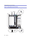
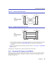
6. Locate the slot guides that line up with the number of the slot in which the module will be
installed. Install the module in the chassis by aligning the module circuit card between the upper
and lower metal rail guides of the desired slot, sliding it into the chassis, and locking down the
top and bottom plastic locking tabs, as shown in Figure 3-1. Take care that the module slides in
straight and properly engages the backplane connectors.
7. If the chassis in which the module is installed was powered down for the installation, turn it back
on. Check to see that the CPU LED settles at solid green after a few minutes. If the LED does
not turn solid green, see Chapter 4 for details.
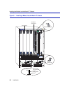
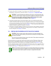
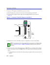
3.4 INSTALLING THE MODULE INTO THE 6C105 CHASSIS
Certain restrictions may apply when installing the module into the 6C105 chassis. Refer to the
Release Notes for any updated information concerning installing the 6H302-48 or 6H303-48
modules into the 6C105 chassis. Otherwise, the installation procedure from Section 3.3 can be
followed, with the exception of the fact that the 6C105 chassis has only 5 slots as opposed to the 7
slots in the Matrix E7. The module can be installed in any of the slots that are available. To install
a module, refer to Figure 3-2 and proceed as in Section 3.3.
CAUTION: To prevent damaging the backplane connectors in the following step, take
care that the module slides in straight and properly engages the backplane connectors.
Ensure that the top plastic locking tab lines up with the desired slot number
located on the front panel of the chassis. Refer to Figure 3-1.
CAUTION: Failure to observe static safety precautions could cause damage to the
module. Follow static safety handling rules and wear the antistatic wrist strap provided
with the 6C105 chassis.
Do not cut the non-conductive bag to remove the module. Sharp objects contacting the
board or components can cause damage.
NOTE: The Distributed Chassis Management and SecureFast Switching functionality is
supported when the modules are installed in a 6C105 SmartSwitch 6000 chassis. Refer
to the module release notes for specific information on supported functionality.