


Installing Optional HSIM or VHSIM Interface Modules
Optional Installations and Mode Switch Bank Settings B-9
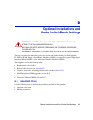
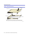
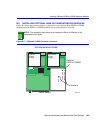
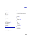
B.5 INSTALLING OPTIONAL HSIM OR VHSIM INTERFACE MODULES
Figure B-5 shows the location of the two connectors for an optional High HSIM or VHSIM.
Depending on the HSIM or VHSIM installed, one or both connectors are used.
Figure B-5 HSIM and VHSIM Connector Locations
NOTE: The installation instructions for the optional HSIM or VHSIM are in the
associated user’s guide.
2504-31
FRONT PANEL
TOP VIEW WITHOUT COVER
Primary
Power
Supply
Redundant
Power
Supply
Optional
HSIM or VHSIM
Connectors