


EPSON PowerLite 5550C/7550C Multimedia Projector
2 -
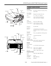
PowerLite 5550C/7550C Multimedia Projector
9/99
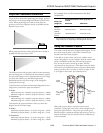
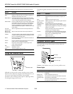
Remote Control
Range 32.8 feet (10 meters)
Batteries Alkaline AA (2)
I/R receiver Supports Xantech
®
IR repeaters,
interface 3.5 mm stereo mini-jack
right/left ± 30°; upper/lower ± 15°
Mouse Compatibility
Supports PS/2, serial, ADB, and 98 Bus
Repeater Interface
Supports Xantech IR repeaters,
standard, 3.5 mm stereo mini-jack
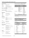
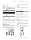
Mechanical
Height 3.7 inches (93 mm)
Width 9.4 inches (238.5 mm)
Depth 13.6 inches (346 mm)
Weight 9.4 lb (4.3 kg)
Electrical
Rated frequency 50/60 Hz
Power supply 100 to 120 VAC (± 10%), 2.2 A,
50/60 Hz
200 to 240 VAC (± 10%), 1.0 A,
50/60 Hz
Power
consumption Operating: 220 W
Standby: 30 W
Noise Level
≤ 42db-A (normal use)
Environmental
Temperature Operating: 41 to 95 °F (5 to 35 °C),
non-condensing
Storage: 14 to 140 °F (–10 to 60 °C),
non-condensing
Humidity Operating: 20 to 80% RH,
non-condensing
Storage: 10 to 90% RH,
non-condensing
Safety
United States FCC Part 15J Class B
UL1950 Rev. 3
Canada DOC SOR/88-475
CSA C22.2 No. 950 Rev. 3
Supported Computers and Monitor Displays
The projector supports the following display formats.
* PowerLite 7550C only.
Note: The frequencies of some computers may not allow the image
to be displayed correctly.
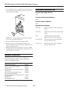
Computer In and Computer Out
Connector Pin Assignments
The Computer In and Computer Out connectors are female
video RGB, 15-pin micro-D-style connectors. The pin
assignments are:
Computer type Formats Resolutions
IBM PC and
IBM PC compatible
EGA
NEC PC 400
VGA60, VESA 72/75/85
VGA Text
VGA Text
SVGA 56/60/72/75/85
XGA 60/70A/75/85
SXGA 70/75
SXGA 85
SXGA 60/75
640
×
350
640
×
400
640
×
480
720
×
350
720
×
400
800
×
600
1024
×
768
1152
×
864
1152
×
864*
1280
×
1024*
Apple Macintosh Standard 8- and 24-bit
color monitor
640
×
480 (13”)
832
×
624 (16”)
1024
×
768 (19”)
1152
×
870 (21”)
EWS 1280
×
1024*
TV NTSC
PAL, PAL60, SECAM
640
×
480
768
×
567
Pin
Computer Out
connector signals
Computer In
connector signals
1 Red analog input Red video
2 Green analog input Green video
3 Blue analog input Blue video
4 Reserved Monitor (ID bit 2)
5GND GND
6 Red GND Red video GND
7 Green GND Green video GND
8 Blue GND Blue video GND
9 Reserved +5 V
10 GND Synchronous GND
11 Reserved Monitor (ID bit 0)
12 Reserved SDA
13 Horizontal sync/composite sync Horizontal sync
14 Vertical sync Vertical sync
15 Vertical sync (SCL)