


LQ - 850/950/1050 DOT - MATRIX PRINTER
Electrical
Voltage
120 VAC, + 10% (USA)
220 VAC,
f
10% (Europe)
Non-switchable
Power consumption
120 Watts maximum
Frequency
49.5 to 60.5 Hz
Insulation resistance
10
MR
between AC power line and chassis
Dielectric strength
120 V model can withstand 1.25
kV
rms applied between AC
line and chassis for 1 minute, or 1.5
kV
rms for
1
second
Environment
Temperature
Operation: 41” F to 95” F
(5”
C to 35” C)
Storage:
-
22” F to
150”
F
(-
30” C to 65” C)
Humidity
Operation: 10% to 80% without condensation
Storage: 5% to 85% without condensation
Shock
Operation: Up to
1
G within 1ms
Storage: Up to 2 G within 1ms
Vibration
Operation: Up to 0.25 G at up to
55
Hz
Storage: Up to 0.5
Cl
at up to
55
Hz
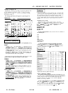
Printing on Special Paper
For printing on special types of paper, see the table below. When
the paper thickness lever is set to position 4 or higher, the MULTI-
PART light comes on and the printing speed is reduced.
The following table gives you general guidelines for selecting the
right paper thickness lever position to match your paper:
Paper Type
Lever Position
2
2
or
1
Paper (single sheets or continuous)
Thin paper
Multi-part paper
P-sheet
3sheet
4-sheet
Labels
Envelopes
Air mall
PIaWl
Bond
I20
lb.1
Bond
(24
lb.1
3
4
5
4
4
4 or 5
6
6
7
8
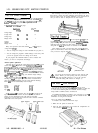
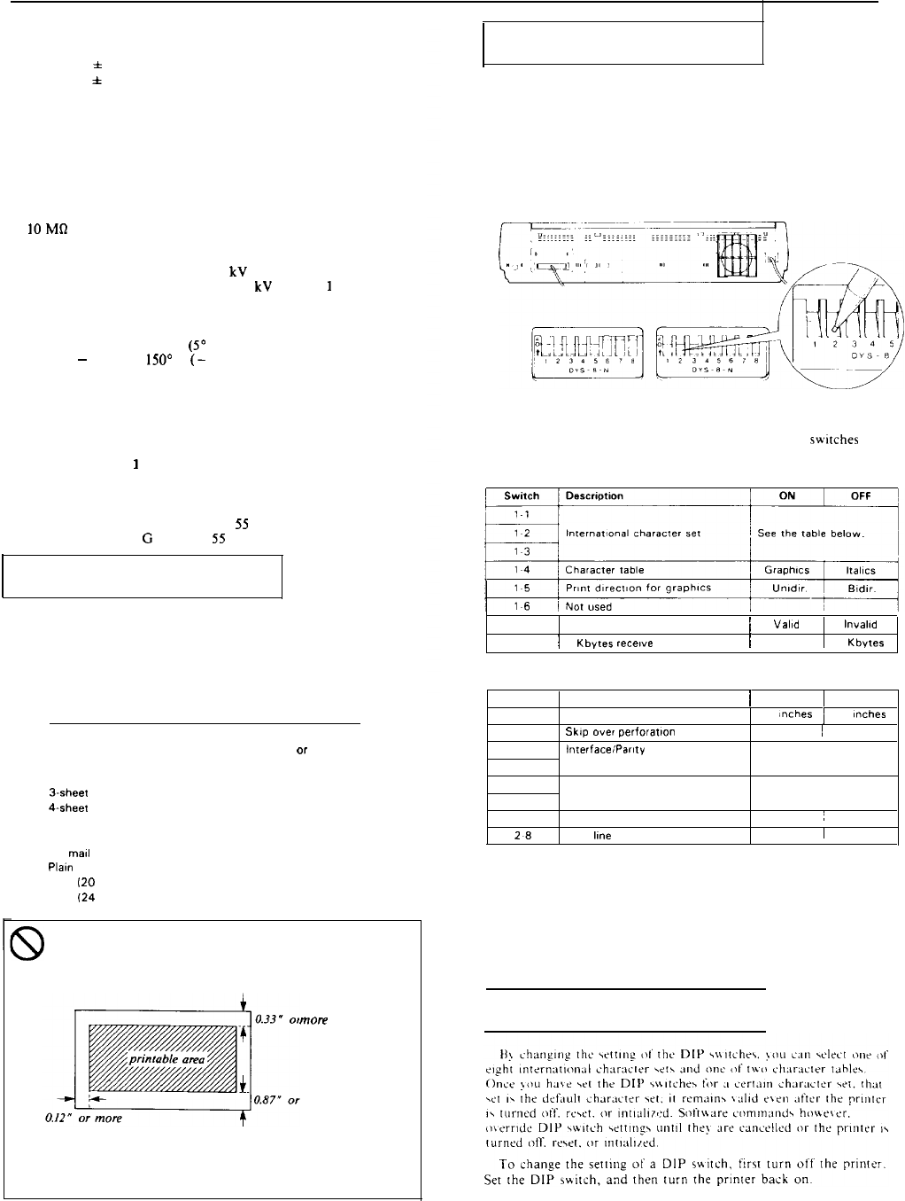
When printing on envelopes, be sure that your application
program settings keep the printing entirely within the
printable area of the envelopes as shown below.
more
more
To make sure that the printing fits within this area, always
perform a sample printing test using a normal single sheet
of paper before printing on envelopes.
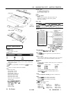
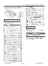
Setting the DIP Switches
By adjusting the settings of the two groups of DIP switches (SW1
and SW2) in the back of the printer, you can control various
features such as character set and page length.
To change the setting of a DIP switch, first turn off the printer.
Using a pencil, pen, or other pointed instrument, change the setting
as shown below. Then, turn the printer back on.
SW 1
SW 2
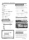
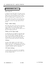
The tables below describe the functions of the DIP switches
DIP Switch 1
17 Cut sheet feeder mode
i
Valid
lnvalld
1.8
I
6
Kbytes
recenve
buffer
1
0 bytes 1 6 Kbytes
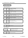
DIP Switch
2
Switch
Description
/
ON 1
OFF
21
Page length
I
12
Inches
1
11
Inches
22
Skip over
perforation
ON
I
OFF
23
InterfaCeiParlty
See the table below
2-4
25
Baud rate
See the table below
26
27
Short tear-off mode
ON
:
OFF
28
Auto
kne
feed
ON
1
OFF
represents the DIP switch settings that have been preset at
the factory.
The factory settings for International character sets (DIP switches
1-1 to 1-3), the Character table (DIP switch 1-4). and Page length
(DIP switch 2-1) vary depending on the country, and are not
shown in the tables above.
Selecting Character Sets
LQ - 850/950/1050 - 2
12/12/88
24 - Pin Printers