


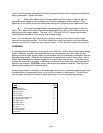
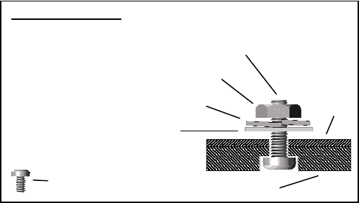
STEP TWO - MOUNT THE MOTORIZED TRANSPORT: Position the flat side of the ATH
Transport against the bottom side (projector side) of the Attachment Plate so that the Transport
connector jacks are toward the projector
and the center “M” hole in the Attachment
Plate is aligned with the front recessed
transport hole. Insert the #10-32 x 5/8
pivot screw up through the Transport and
Attachment Plate and loosely complete
the assembly with the corresponding
washer, lock washer and nut. Now
loosely insert the four small 3/8” screws
through the four remaining “M” slots
through the top of the Attachment Plate
and down into the Transport.
Motorized Transport
P
#10-32x5/8” screw (1)
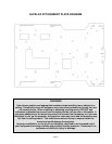
STEP THREE – PREP THE RPA ATTACHMENT SCREWS: Insert a black socket
head screw through a silver 3/8” spacer into each of the six threaded holes in the top of
the Attachment Plate. Insert these screws only enough to reach through to the bottom
of the Attachment Plate.
STEP FOUR – MOUNT THE PROJECTION ASSEMBLY: Ensure that the RPA mount
head is secure and oriented properly relative to the Attachment Plate RPA screws so that the
mounted projector will face the screen. Use two people to lift and position the projection
assembly so that the heads of each of the Attachment Plate RPA screws rest within the
matching final location of the RPA mount head. At this point the silver 3/8” spacers should be
between the Attachment Plate and the RPA mount head. The projection assembly may be
lowered to allow the RPA screw heads to rest on the RPA mount. However, one person should
continue to support the projection assembly while a second person uses the gold hex key
wrench to tighten the RPA screws.
When tightening the RPA screws, do so in a pattern of incrementally driving each screw a little
more into the attachment plate so that at any time the projection assembly is resting on as many
screw heads as possible until all are tightened.
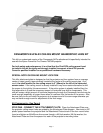
STEP FIVE – INSTALL THE LENS: Refer to the Transport user manual for additional
instructions to install the lens at this time. REMEMBER TO COMPLETE THE LAST STEP
BELOW.
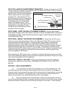
STEP SIX – FINAL ADJUSTMENTS:
a. Turn the projector on with the anamorphic lens out of the projector beam. Set
the horizontal lens shift to neutral and then adjust the RPA mount so that the 16:9 image is in
the exact center of and square to the screen with a similar amount of image slightly over the top
and bottom screen borders. If the projector lens is not in the exact horizontal center of the
screen you may need to use a little horizontal lens shift for this purpose.
b. Bring the anamorphic lens into the beam. Adjust the vertical position and tilt of
the lens so that the projector beam is passing through the center of the lens and so any residual
pincushion distortion is about the same at the top and bottom of the image. This will typically
#6-32x3/8” screw (4)
#10-32 lock washer (1)
#10-32 washer (1)
#10-32 nut (1)
ivot screw as
assembled
Attachment
Plate
Transport
Page 3