RTC - 4543 SA/SB
Page - 6 MQ - 252 - 03
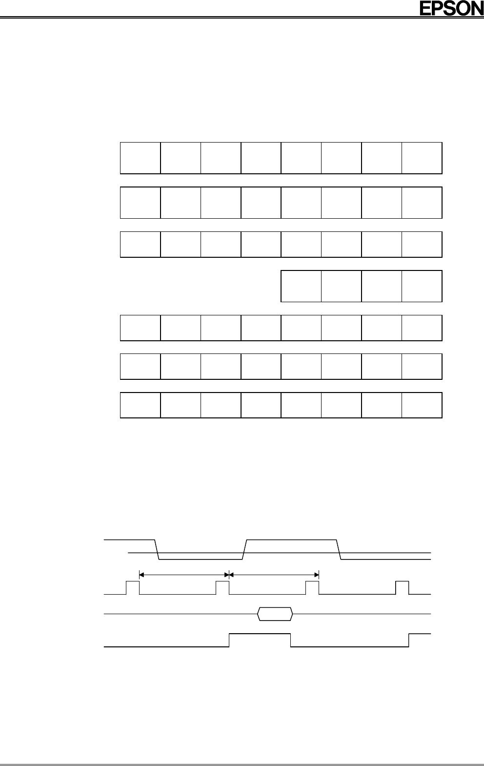
6. Timer Data Organization
•
The counter data is BCD code.
•
The timer automatically adjusts for different month lengths and for leap year.
•
The time is indicated in 24-hour format.
•
Writes and reads are both performed on an LSB-first basis.
MSB LSB
Second
( 0 to 59 )
FDT
s40
s20
s10
s8
s4
s2
s1
Minutes
( 0 to 59 )
*
mi40
mi20
mi10
mi8
mi4
mi2
mi1
Hour ( 0 to 23 )
*
*
h20
h10
h8
h4
h2
h1
Day of the week
( 1 to 7 )
*
w4
w2
w1
Day ( 1 to 31 )
*
*
d20
d10
d8
d4
d2
d1
Month ( 1 to 12 )
TM
*
*
mo10
mo8
mo4
mo2
mo1
Year ( 0 to 99 )
y80
y40
y20
y10
y8
y4
y2
y1
* bits: Any data may be written to these bits.
•
FDT bit: Supply voltage detection bit
•
This bit is set to “1” when voltage of 1.7
±
0.3 V or less is detected between V
DD
and GND.
•
The FDT bit is cleared if all of the digits up to the year digits are read.
•
Although this bit can be both read and written, normally set this bit to “0”.
D
etect
i
on
pulse
V
DD
Mode
FDT bit
V
DET
0.5 s
Read
0.5 s
The supply voltage detection circuit monitors the supply voltage once every 0.5 seconds;
if the supply voltage is lower than the detection voltage value, the FDT bit is set to “1”.
•
TM bit: This is a test bit for SEIKO-EPSON’s use. Always set this bit to “0”.


