


S5U1C63000H2 MANUAL EPSON 15
(S1C63 FAMILY IN-CIRCUIT EMULATOR)
CHAPTER 5: OPERATION AND FUNCTION OF S5U1C63000H2
5.8 Trace Mode
There are following three trace modes.
(1) All bus cycle trace mode
In this trace mode, all bus cycles are traced during run emulation and step emulation until a break
occurs.
(2) Specified PC range trace mode
In this mode, bus cycles within the specified range (or outside the specified range) are traced during
run emulation and step emulation until a break occurs. This function is useful for cases of tracing
objective work data only or removing WAIT routine from the trace.
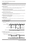
(3) Single delay trigger
In this mode, starting a run emulation starts tracing all bus cycles. When the emulation hit the trace
trigger condition, the trace continues for the specified bus cycles, and then it stops. The trace informa-
tion is displayed after a break.
In the debugger, one of the above modes can be selected by the TM command.
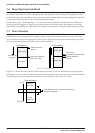
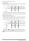
5.9 Trace Trigger Point
In the S5U1C63000H2, a trace trigger point can be specified independent of breaking points. The trace
trigger point is specified as the program counter conditions of the S1C63000 CPU. A low level pulse is
output from the TRGOUT terminal with the timing of T3 upon coincidence of the specified value and the
program counter. The information of the trace trigger point is also stored into the trace memory. In the
single delay trigger mode, the trace trigger point becomes a condition for stopping the trace.
5.10 Coverage Function
The S5U1C63000H2 can retrieve and display the address information of the program accessed at the
execution. The confirmation of portions whether failure analysis or debugging is completed or not can be
done by checking the program through reference of the coverage information after running the program
for a long time. This function is specified by the CV or CVC commands.
5.11 Measurement of Execution Time
The S5U1C63000H2 has a function to measure the time from start to break of target programs or to count
the bus cycles. This function is set by the MD command.
(1) Time measurement mode
(a) Range of time measurement
1 µsec to 1∗(2
31
-1) µsec (≈ 2,147 sec ≈ 36 minutes)
(b) Measurement error
±1 µsec
(c) Units of time display
Micro second (µsec)
(2) Bus cycle count mode
(a) Range of cycle measurement
1 bus cycle to (2
31
-1) bus cycles (= 2∗10
9
bus cycles)
(b) Measurement error
0 cycle