


Optional Antenna Extension
In some installation scenarios, it may be desirable to enhance the switch's wireless (RF)
transmission capabilities. This may be needed to overcome issues such as local
interference from other devices, range considerations due to the distance between devices
or the use of metallic faceplates. The Escient Wireless Switch has been designed with a
wire whip antenna coiled underneath the plastic button that can be extended to
accommodate such scenarios. Instructions for extending the antenna are provided below.
WARNING! To avoid risk of electrical shock that may cause personal injury or
damage to the switch, this procedure should be performed prior to connecting the
switch at the wall box.
CAUTION! Risk of Equipment Damage. This procedure enables advanced
functionality and should only be performed by a competent trained installer.
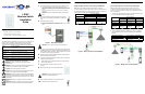
1 Remove the plastic button frame by squeezing
the side tabs near the top and bottom of the
button and pulling outward. A small flat-head
screw driver can also be used to assist in
releasing the tabs.
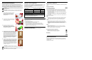
2 Once the button has been removed, detach the
radio board from its connector by gently pulling
away from the switch frame.
3 Slip the end of the antenna out of the radio
board hole and uncoil it, being careful not to
exert undue tension on the wire. Once uncoiled,
thread the antenna wire under the plastic spacer
at the bottom of the radio board.
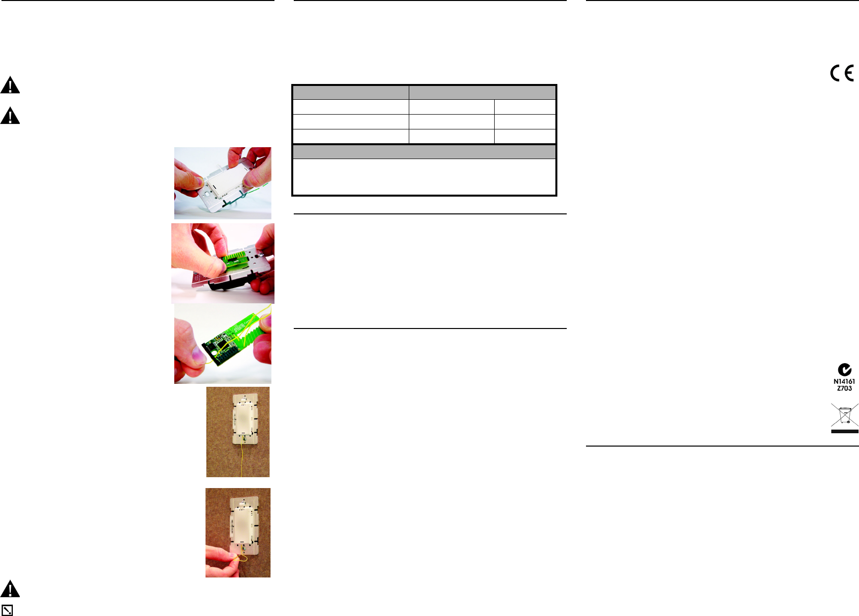
4 Re-attach the radio card to the switch frame by
carefully aligning the connector and pressing gently. Then
re-attach the button and button frame by aligning the
button frame securement tabs with the appropriate slots on
the switch frame and pushing gently. Ensure that the
antenna is routed through the small notch on the bottom
left-hand side of the button frame provided for this
purpose. Once the button has been re-attached, proceed
with the standard installation procedure for wiring the
switch to the light load and securing it into the wall box, as
described in Step 1
through Step 7 of “Installation
Instructions.”
5 The antenna has been designed to extend well beyond the
faceplate. For optimal performance, it should be oriented
in a vertical plane below the switch. To enable this without
leaving the antenna visible to the end user, a very small
hole should be made in the wall just below the switch
frame and the antenna inserted through the hole back into
the wall. Once the antenna has been routed into the wall,
proceed with standard installation (Step 8
through Step 10
of “Installation Instructions.”
CAUTION! Risk of Equipment Damage. The antenna
must not be inserted into the junction box containing high voltage wires.
IMPORTANT! Do not shortened or cut the antenna in any way as this
may seriously impair transmission capabilities.
Operation and Configuration
On initial power up, the unit will flash the Red/Green/Blue (RGB) LEDs, which
can be programmed with different colors for different states or color
preferences. To set up this switch for use with a Escient system, refer to your
system setup documentation.
To operate this switch as a stand-alone device, refer to the following tables.
Troubleshooting
If light does not turn on:
• Ensure at least one LED is lit.
• Ensure light bulb is not burned out and is screwed in tightly.
• Ensure circuit breaker is not turned OFF or tripped.
• Check for proper wiring (see the “Sample Wiring Configurations”section).
• For help on the installation or operation of this product, email or call the DMi
Technical Support Center. Please provide your exact model number. Contact
info@dm-i.eu or see the web site www.dm-i.eu
Limited 2 Year Warranty
Limited 2-year Warranty. Refer to www.escienteurope.com/warranty
Regulatory Compliance
This product complies with standards established by the following regulatory
bodies:
European Compliance
CE Declaration of Conformity
Product: 240 Volt Wireless Switch
The undersigned hereby declares, on behalf of Escient, that the above-referenced
product, to which this declaration relates, is in conformity with the provisions of:
• Council Directive 89/336/EEC (May 3, 1989) on Electromagnetic Compatibility
• Council Directive 1999/5/EC (Mar 9, 1999) on Radio & Telecommunication Ter-
minal Equipment (R&TTE)
• Council Directive 2006/95/EC (Dec. 12, 2006) on Low Voltage Equipment Safety
• Council Directive 93/68/EEC (Jul. 22, 1993) Amending Directives 89/336/EEC
and 73/23/EEC
and has been tested to the requirements of, and shown to be in compliance with, the
following requisite standards:
EMC
• ETSI EN301489-1 and EN301489-17 Electromagnetic compatibility and Radio
spectrum Matters (ERM); ElectroMagnetic Compatibility (EMC) standard for
radio equipment and services: Part 1: Common Technical requirements
Radio
• ETSI EN300328 Electromagnetic compatibility and Radio spectrum Matters
(ERM); Wide band transmission systems; Data transmission equipment operat-
ing in the 2.4GHz ISM band and using wide band modulation techniques;
Harmonized EN covering essential requirements under article 3.2 of the R+TTE
Directive.
Safety
• EN60669-1 Switches for household and similar fixed electrical installations -
Part 1: General requirements
• EN60669-2-1 Switches for household and similar fixed electrical installations -
Part 2-1: Particular requirements - Electronic switches
Australian/New Zealand Compliance
• AS/NZS 4268:2003 Radio equipment and systems
• AS/NZS 4771:2000 Data transmission equipment
Recycling
About this Document
Copyright © 2004-2009 Escient. Escient and the Escient logo are registered
trademarks of D&M Holdings, Inc. All other trademarks are properties of their
respective owners.
Part Number: LS102_0809
Operate Switch Expected behavior of RGB LEDs:
To operate switch: Top Bottom
Turn ON: Tap top. Lit, full brightness Not lit
Turn OFF: Tap bottom. Not lit Lit, full brightness
Care and Cleaning
Do NOT paint switch or its wall plate.
Do NOT use any chemical cleaners to clean the switch.
Clean surface with a soft damp cloth as needed.