


MI00/10056 rev.1--05/2001-- page 25
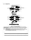
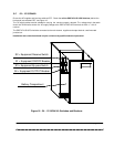
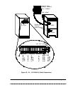
5.0 CONNECTION
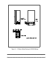
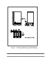
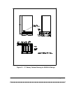
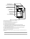
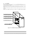
Figure 15 – Connection diagrams
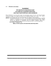
THE AC AND DC SUPPLIES TO THE EDP70 PLUS UPS, AND THE AC OUTPUT FROM THE UPS, SHOULD BE FED
THROUGH SUITABLY RATED CIRCUIT BREAKER OR FUSE(S) AND ISOLATING SWITCH SUITABLE FOR BRANCH
CIRCUIT PROTECTION.
NOTE: INTERRUPTING THE NEUTRAL FEED MAY CAUSE THE CHANGE IN GROUND-NEUTRAL VOLTAGE TO
AFFECT THE LOAD.
NOTE: ALL CIRCUIT BREAKERS OR FUSES AND ISOLATING SWITCHES SHOULD BE FITTED AS CLOSE TO THE
EDP70 PLUS UPS AS POSSIBLE AND MARKED WITH THE LABELS PROVIDED WITH THE UNIT.
IT IS ALSO RECOMMENDED A LABEL AS FOLLOWS
Protection devices to be installed by the customer
EXTERNAL
BATTERIES
Protection devices to be installed by the customer
according to the information shown on page 23
according to the information shown on page 23
OUTPUT
OUTPUT
EXTERNAL
BATTERIES
Remove link to connect remote E.P.O.
Remove link to connect remote E.P.O.
Neutral not
present on
50 and 80kVA
ratings
(Neutral separately derived
on 50 and 80kVA ratings)
(Neutral separately derived
on 50 and 80kVA ratings)
UTILITY
INPUT
INPUT
RESERVE
L1
L2
L3
L1
L2
L3
N
UTILITY
INPUT
L1
L2
L3
N
6
GROUND
Neutral not
present on
50 and 80kVA
ratings
A
B
C
G
A
B
C
N
1
2
3
4
5
A
B
C
N
Thermostick contacts
Battery Charge Inhibit
L1
L2
L3
N
GROUND
G
1
2
3
4
5
6
A
N
C
B
N
A
B
C
Thermostick contacts
Battery Charge Inhibit
N
L1
L2
L3