


C
o
T
c
o
C
o
P
l
L
US
B
o
nnectin
g
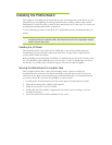
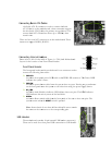
S
T
he Serial
A
A
TA II de
v
the thin Se
current Se
r
transfer ra
t
T
here are four
o
nnectors su
p
o
nnectin
g
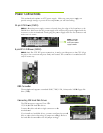
I
l
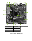
ease refer to
ayout for the
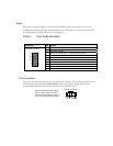
Front Pa
n
T
he front
p
connect th
PWRL
A
ttac
h
indica
t
PWRS
A
ttac
h
on the
HD_L
E
A
ttac
h
LED i
n
RESE
T
A
ttac
h
syste
m
Note:
the na
m
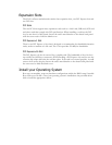
B
Headers
T
he moth
e
T
hese can
S
erial ATA
C
A
TA II conn
e
v
ice to the m
o
rial ATA II c
a
r
ial ATA II in
t
t
e.
serial AT
A
c
o
p
port RAID 0
nternal He
a
#9 of in the
t
location of t
h
n
el Header
p
anel header
o
e following f
o
ED
h
the front pa
n
t
es the system
W
h
the power b
u
front panel t
u
E
D
h
the hard dis
k
n
dicates the
a
T
h
the Reset s
wi
m
restarts whe
n
Some chassis
m
e on the co
n
e
rboard conta
i
be used for a
C
ables
e
ctor
i
s used
t
o
therboard.
T
a
bles for pri
m
t
erface allows
o
nnectors on
t
, RAID 1.
a
ders
t
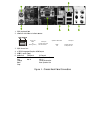
able of Figur
e
h
e Front Pane
l
o
n this moth
e
o
ur cables:
n
el power LE
D
’s status.
u
tton cable fr
o
u
rns the syste
m
k
drive indica
t
a
ctivity status
o
w
itch cable fro
m
n
the
RESET
s
do not have
a
n
nectors to t
h
i
ns 10-pin int
e
front panel
U
t
o connect th
e
T
hese connect
o
m
ary storage d
e
up to 300M
B
t
he motherb
o
e
1. e-7010/6
1
l
Headers.
e
rboard is one
D
cable to th
e
o
m the case t
o
m
on off rath
t
or LED cabl
e
o
f the hard di
m
the front p
a
s
witch is pres
s
a
ll four cable
s
h
e correspond
i
e
rnal USB he
a
U
SB connecti
o
e
Serial
o
rs support
e
vices. The
B
/s data
o
ard. These
1
0i Motherbo
a
connector us
e
PWR LED
c
o
these two p
i
er than using
e
to these two
sks.
a
nel of the ca
s
s
ed.
s
. Be sure to
m
i
ng pins.
a
der connect
o
o
n or USB br
a
a
rd
ed to
c
onnector.
Th
i
ns. Pressing t
h
the power su
p
pins. The H
D
s
e to these t
w
m
atch
o
r(s).
a
cket.
h
e Power LE
D
h
e powerbutt
o
p
ply button.
D
D indicator
w
o pins. The
D
o
n