


EVGA X58 SLI Motherboard
EVGA | 25
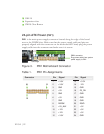
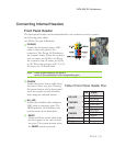
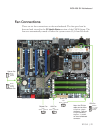
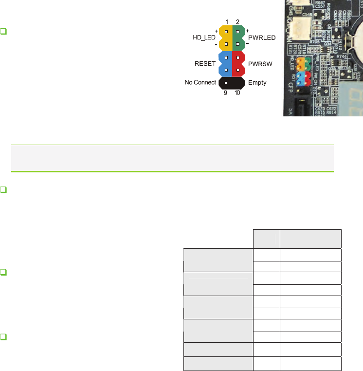
Connecting Internal Headers
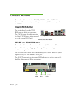
Front Panel Header
The front panel header on this motherboard is one connector used to connect
the following four cables.
(see Table 2 for pin definitions):
l four cables. Be sure to match the
Table 2.Front Panel Header Pins
Pin Signal
1 HD_PWR
HD_LED
3 HD Active
2 PWR LED
PWRLED
4 STBY LED
5 Ground
RESET
7 RST BTN
6 PWR BTN
PWRSW
8 Ground
No Connect 9 +5V
Empty 10 Empty
PWRLED
Attach the front panel power LED
cable to these two pins of the
connector. The Power LED indicates
the system’s status. When the system is
turn on status, the LED is on. When
the system is turn off status, the LED
is off. When the system is in S1, S1, S3,
S4 status, the LED will blink.
Note: Some system cases do not have al
name on the connectors to the corresponding pins.
PWRSW
Attach the power button cable from
the case to these two pins. Pressing
the power button on the front panel
turns the system on and off rather
than using the onboard button.
HD_LED
Attach the hard disk drive indicator
LED cable to these two pins. The
HDD indicator LED indicates the
activity status of the hard disks.
RESET
Attach the Reset switch cable from
the front panel of the case to these
two pins. The system restarts when
the
RESET switch is pressed.