


Extron • Model 8 PLUS & Model 10 PLUS Switchers • User’s Manual Page 2-6
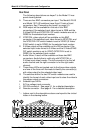
12345678
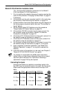
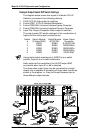
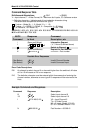
Example Output Select DIP Switch Settings
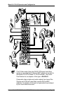
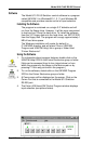
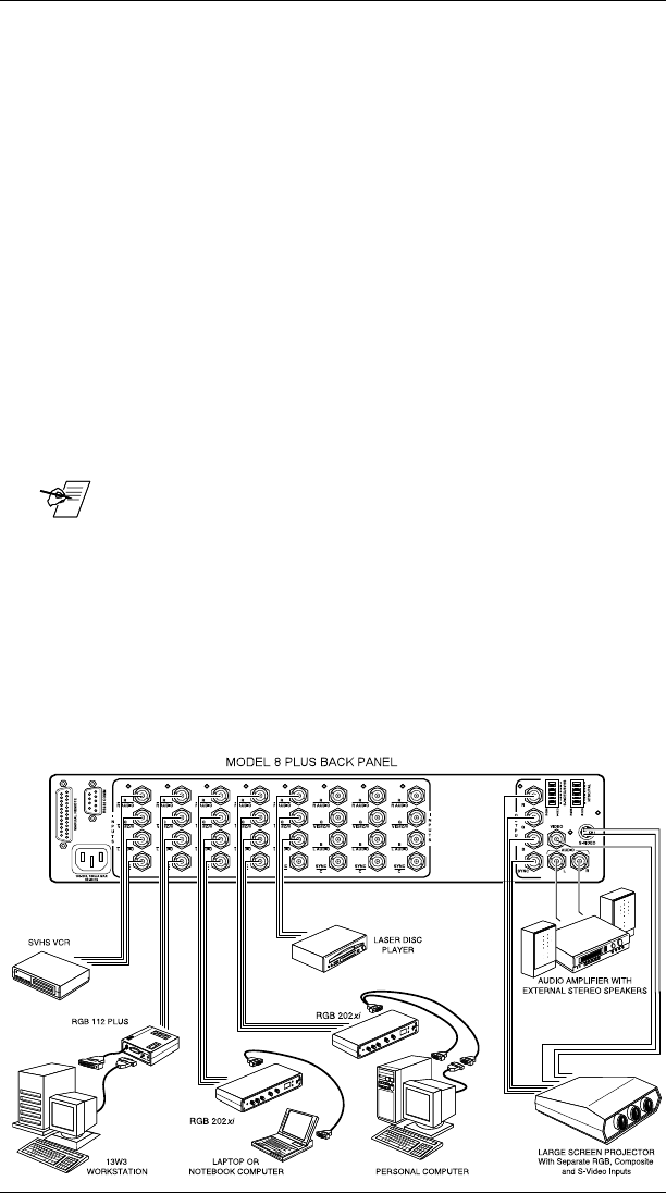
The diagram below shows five inputs of a Model 8 PLUS
Switcher connected to the following devices:
1. SVHS VCR (S-Video output to switcher)
2. Extron RGB 112 PLUS Interface/Workstation
3. Extron RGB 202xi Universal Interface/Laptop Computer
4. Extron RGB 202xi Universal Interface/Personal Computer
5. Laser Disc Player (Composite Video output to switcher)
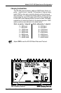
The output select DIP switch settings for this combination of
inputs and the valid output connectors are:
Switch Switch Module Switch Module Video Output
# S-Video/SVHS NTSC/PAL Connector
1 VIDEO RGBS S-VIDEO DIN
2 RGBS RGBS RGBS BNCs
3 RGBS RGBS RGBS BNCs
4 RGBS RGBS RGBS BNCs
5 RGBS VIDEO VIDEO BNC
_ Having both switch modules set to VIDEO for any switch
position (Input #) is an invalid combination.
Audio output will be available at the AUDIO output BNC
connectors when input #1 or #5 is selected.
The three video output types can be connected to a single
display that is capable of accepting all three video formats as
shown in the diagram, or, they can be split between two or
three different output devices.
Model 8/10 PLUS Operation and Configuration