


5
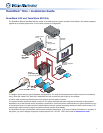
Installation
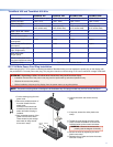
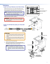
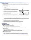
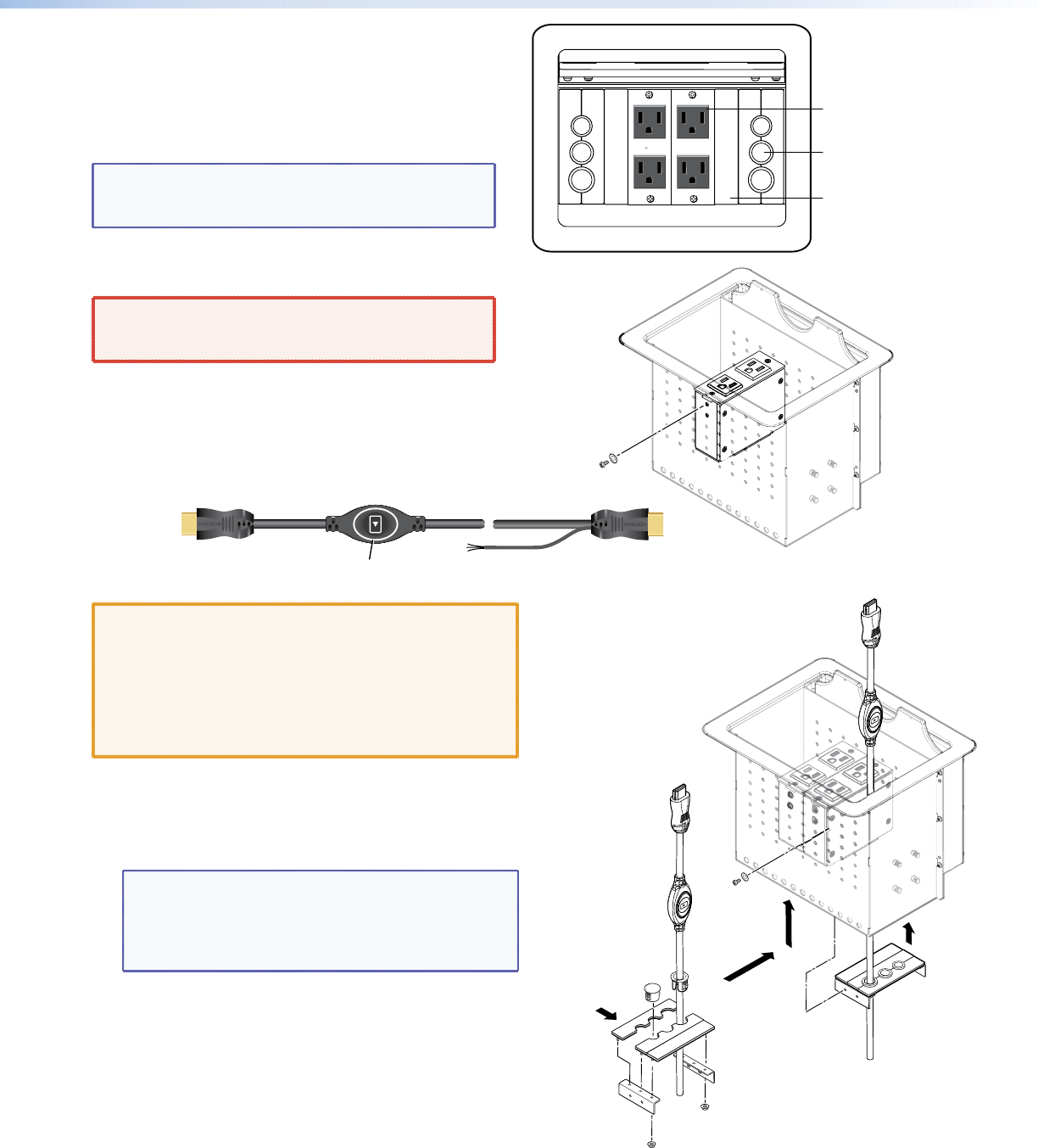
Install the Power Modules in the Cable Cubby
Detailed instructions are in the Cable Cubby Setup Guide.
Extron recommends the layout shown to the right with AAP
shelf assemblies on either side of the power modules.
NOTE: Depending on your country, a power module
may occupy two or three AAP spaces, so your nal
conguration may look slightly different.
Secure the power modules in position with the provided #4-40
Phillips head screws and star washers.
WARNING: Possible electric shock: To ensure good
electric grounding, you must use the star washers
with the screws.
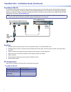
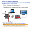
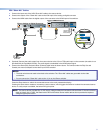
Install the AAP Shelf Assembly and “ShowMe”
Cables
INPUT
(to source device)
Top of Cable Cubby
OUTPUT
(to switcher)
Bottom of
Cable Cubby
Share Button
Three-conductor
pigtail for contact
closure and tally
ATTENTION:
• The end with the button and LED connects to the input
devices and must come out of the top of the Cable
Cubby.
• The end with the three-conductor pigtail connects to
the switcher and must come out of the bottom of the
Cable Cubby.
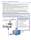
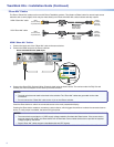
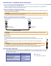
1. Assemble the AAP shelf assembly.
2. Insert the AAP assemblies into the Cable Cubby from
underneath and secure them in position with the provided
#4-40 Phillips head screws and star washers.
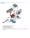
NOTE: The diagrams on this page show how to
install HDMI “Show Me” cables in the AAP Shelf
Assembly. If you are using the TeamWork VGA kit,
install VGA “Show Me” cables in exactly the same
way.
125 50/60HZ
5A EACH
UNSWITCHED
125 50/60HZ
5A EACH
UNSWITCHED
Power Module
AAP Shelf Assembly with
Cable Pass-through
Blank AAP
Split Grommet
“Show Me” Cable
“Show Me” Cable
“Show Me” Cables
must be inserted into
shelf assemblies as
it is being constructed.
Plug
AAP Shelf
Assemblies
Shelf
Brackets
a
b