


RGB 460
xixi
xixi
xi/472
xixi
xixi
xi/AAP 102 FSR Series • Installation GuideRGB 460
xixi
xixi
xi/472
xixi
xixi
xi/AAP 102 FSR Series • Installation Guide
Installation, cont’d
2
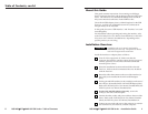
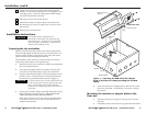
Figure 1 — Securing the RGB 460xi FSR adapter
plate to the floor box and grounding the braided
shield
5. Secure the interface or adapter plate to the floor box with
the screws provided. See Mounting the interface or adapter
plate below.
Mounting the interface or adapter plate to the
floor box
1. Disconnect the power supply to remove power from the
interface.
2. If installed, remove the floor box’s top panel and trim frame.
3
8
The picture should now appear, and sound should be
audible. If not, ensure that all devices are plugged in and
receiving power. Check the cabling and switch settings,
and make adjustments as needed.
9
Disconnect power from all the devices.
10
Mount the interface or adapter plate into the floor box.
See Mounting the interface or adapter plate to the floor box in
this manual.
11
Restore power to the devices.
Installation Instructions
CAUTION
The interface must be installed into an
Underwriters Laboratories (UL) approved FSR
electrical floor box. The floor box is not included
with the interface; the installer is responsible for
obtaining and installing the box.
Preparing the site and cables
Choose a location that allows cable runs without interference.
Allow enough depth for both the floor box and the cables. You
need to run the conduit (if required by local code) and cables
under the floor before installing the interface.
The installation must conform to national and local electrical
codes and to the interface’s size requirements.
1. Install the floor box in accordance with the documentation
that accompanied the box.
2. Feed cables through the floor box punch-out holes, and
secure them with cable clamps to provide strain relief.
3. Exposed cable shields (braids or foil) are potential sources
of short circuits. Trim back and/or insulate shields with
heat shrink, or ground the shield to the box (figure 1).
CAUTION
To prevent short circuits, the outer foil shield can be
cut back to the point where the cable exits the cable
clamp. Both braided and foil shields should be
connected to an equipment ground at the other end
of the cable.
4. Set the gain and DIP switches and cable and test the device
before securing it into the floor box. The switches and
cables will be inaccessible after installation.
Refer to the RGB 400
xi
Series User Manual, Part #68-542-01
or the RGB 470xi Series User Manual, Part #68-661-01 for
additional information.
RGB 460xi FSR
IN
P
U
T
M
O
N
IT
O
R
H
. SH
IF
T
MIN/M
A
X
AU
D
IO
N
O
M
O
N
IT
O
R
M
O
N
I
T
O
R
Screw
Braided Shield
Installation
Cable
Mounting Plate
RGB 460xi FSR
FSR Box
Plastic Filler Strip
(optional)