


RGB 460
xixi
xixi
xi/472
xixi
xixi
xi/AAP 102 FSR Series • Installation GuideRGB 460
xixi
xixi
xi/472
xixi
xixi
xi/AAP 102 FSR Series • Installation Guide
Installation, cont’d
5
Temperature/humidity .............. Storage -40° to +158°F (-40° to +70°C) /
10% to 90%, non condensing
Operating +32° to +122°F (0° to +50°C) /
10% to 90%, non condensing
Rack mount................................... No, but FSR floor box mountable
Enclosure type.............................. Metal
Enclosure dimensions
RGB 460xi/472xi FSR
Plate.......................... 4.5" H x 3.6" W (11.4 cm H x 9.1 cm W)
Back enclosure ........ 2.7" H x 3.3" W x 1.1" D
(6.9 cm H x 8.4 cm W x 2.8 cm D)
(Depth excludes front panel connectors
and controls.)
AAP 102 FSR .................... 4.5" H x 3.6" W (11.4 cm H x 9.1 cm W)
Specifications are subject to change without notice.
Included Parts
These items are included in each order for the indicated interface:
Included parts Part number
RGB 460xi FSR, black 60-373-40
RGB 472xi FSR, black 60-515-40
AAP 102 FSR 60-301-40
12VDC, 1.0A external power supply kit 70-055-01
RGB 400xi Series User’s Manual 68-542-01
RGB 470xi Series User’s Manual 68-661-01
Plastic filler strip 100-216-01
RGB 400xi FSR Series Installation Guide
Accessories
Accessories Part number
3.5 mm stereo plug 10-306-01
Mac/VGA adapter 26-340-01
Mac HV/VGA adapter 26-340-02
Mac 35/VGA 6’ adapter 26-287-01
SY VGA/XGA adapter 26-173-01
SY 15 HDM RGBHVF 26-397-01
4
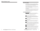
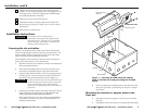
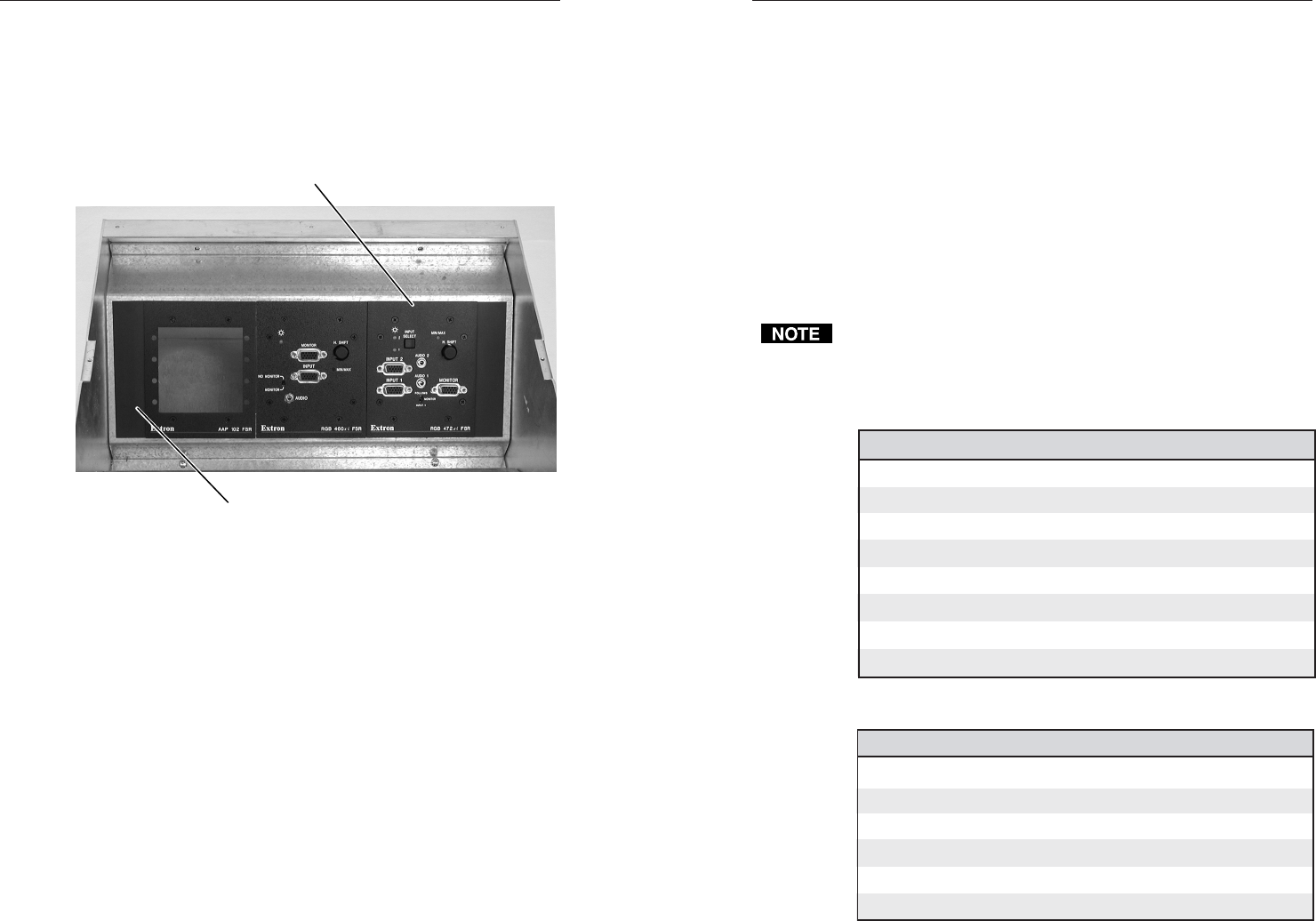
3. Place the interface or adapter plate through the opening in
the floor and into the floor box. Take care not to damage
the cables, which lay behind the interface in the bottom of
the box.
4. Mount the interface or adapter plate(s) to the floor box
with the included machine screws.
Figure 2 — AAP 102 FSR, RGB 460
xi xi
xi xi
xi
FSR
,,
,,
,
and RGB
472
xixi
xixi
xi
FSR installed
5. If necessary, install a plastic filler strip (included with the
interface or adapter plate) to fill the gap when the devices
are installed in either end position (right or left).
6. Install the floor box’s top panel and trim frame.
7. Reconnect the power supply.
Specifications
This guide shows power requirements and physical
specifications only. For electrical and functional specifications,
refer to the RGB 400
xi
Series User Manual, Part #68-542-01 or the
RGB 470
xi
Series User’s Manual, Part #68-661-01, depending on
the specific product you are using.
General
Power............................................. 12VDC, 0.42 A, 5 watts, external (the
power supply is included.)
Install the faceplate with four
machine screws (included).
Install the plastic filler
strips (optional).