Refer to www.extron.com for the
complete TLP 710 series user manual and
installation instructions before connecting
the product to the power source.
1
Product Category
Refer to www.extron.com for the
complete TLP 710 series user manual and
installation instructions before connecting
the product to the power source.
BB 710M • Installation Guide
Overview
The Extron BB 710M back box is used to mount an Extron TLP 710MV TouchLink
™
panel in a wall. This Installation Guide
provides instructions for an experienced installer to retrofit the box in existing drywall or mount the back box in a new
installation. For complete instructions about installing and calibrating the TouchLink panel, see the TLP 710MV and
TLP 710TV User Guide, which are available on the Extron web site (www.extron.com).
Retrot an Existing Installation (with the Drywall in Place)
1. Separate and remove the endplates (top and bottom) from the U-plate (sides and
back).
2. Use the back face of the U-plate to mark the position where the hole will be cut. Use a
level to ensure the U-plate is level.
NOTE: The hole is 7.7 inches (19.5 cm) wide x 6 inches (15.1 cm) high.
3. Using a drywall saw, carefully cut a hole where the touchpanel will be installed. Cut on
the lines that you marked in step 2.
4. Run the cable conduit through the wall. The conduit can be attached to any of the
available knock-out holes in the top, bottom, or either side. Leave some slack to
connect the conduit to the back box and the cables to the touchpanel.
5. Run cables to the installation site.
6. Clear the cables and conduits from the space behind the hole.
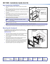
7. If required, secure a conduit to the U-plate and insert the U-plate
into the hole (see figure 1).
NOTE: The U-plate tabs sit on the outer face of the drywall.
8. Pull back the cables that were cleared out of the way in step 5.
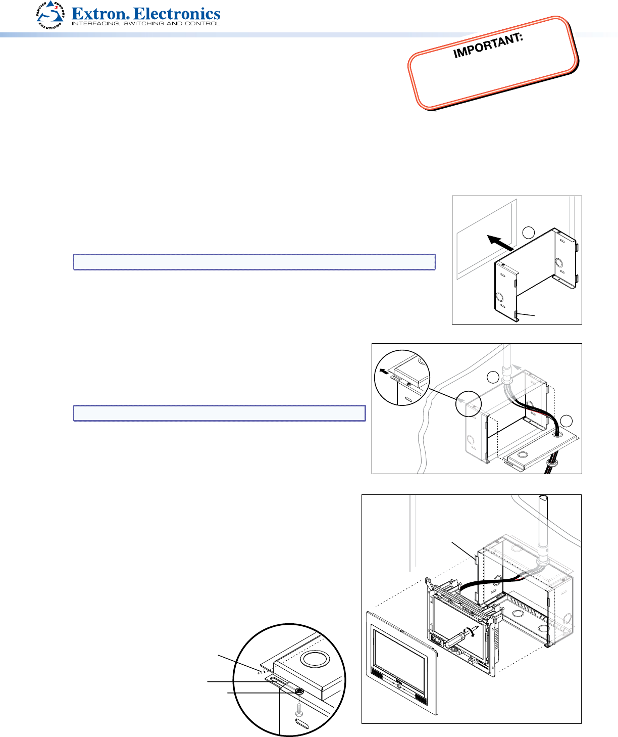
9. If required, secure one or more conduits to the knock-out holes in
the endplate (see figure 2). Break off the lip on the leading edge
of the endplate (see figure 3) to make it easier to maneuver the
endplate with a conduit attached.
10. Slide the endplates into the gap between the back of the U-plate
and the top flanges on the side of the U-plate (see the inset in
figure 2). The endplate must pass the drywall so that the trailing
edge can be pushed in behind it.
11. Secure the endplate to the U-plate, using the four provided
screws. Insert the provided screw from inside the BB 710M,
through the slot in the endplate and into the threaded hole in
the top of the U-plate (see figure 3).
The endplates (behind) and the tabs of the U-plate (in front)
clamp the drywall, holding the BB 710M securely in place.
12. Finish installing the
TouchLink panel
as shown in figure
4 and described
in “Mounting the
Touchpanel” on the
next page.
9
10
Figure 1.
Figure 2.
7
Tabs (4)
BB 710M
U-plate
Figure 4.
Bezel snaps to unit
(4 places on each side).
Tighten screws to
rotate locking arms.
Tabs are against
outside surface
of drywall.
Figure 3.
Slot
Lip Snaps
Off
Threaded
Hole