


Cable Cubby
®
Products • Maintenance and Modifi cations
Maintenance and Modifi cations, cont’d
3-10
Cable Cubby
®
Products
4
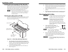
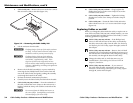
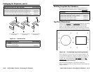
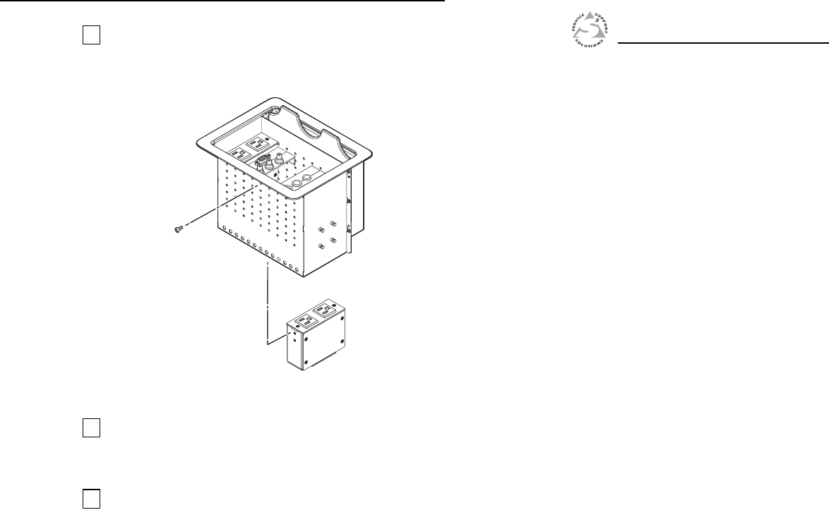
From the underside of the Cable Cubby, gently push the
additional power module into the desired position at the
desired elevation. Secure the power module into position
with the included four Phillips head screws (fi gure 3-7).
2 Screws ea. side
Extron
Cable Cubby 600
Figure 3-7 — Installing the power module
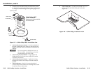
5
If desired, assemble and install replacement AAP shelf
assemblies. Remember that the cable pull function of the
Cable Cubby requires at least two AAPs. See Installing the
Cables and AAPs in chapter 2, Installation.
6
If you removed the cubby from the table, reinstall the
surface mount enclosure. See Removing and Replacing the
Cable Cubby, steps 8 through 11, earlier in this chapter.
A
Appendix A
Reference Information
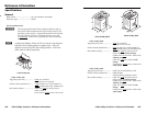
Specifi cations
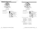
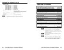
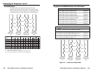
Cable Cubby Part Numbers
Included Parts
Replacement/Modifi cation Part Numbers
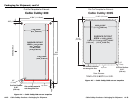
Routing Template Part Numbers
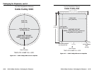
Top Plate Dimensions