


Setup Guide for AVTrac
™
Demonstration Kit, cont’d
PRELIMINARY
©
2009 Extron Electronics. All rights reserved.
Extron USA - West
Headquarters
+800.633.9876
Inside USA / Canada Only
+1.714.491.1500
+1.714.491.1517 FAX
Extron USA - East
+800.633.9876
Inside USA / Canada Only
+1.919.863.1794
+1.919.863.1797 FAX
Extron Europe
+800.3987.6673
Inside Europe Only
+31.33.453.4040
+31.33.453.4050 FAX
Extron Asia
+800.7339.8766
Inside Asia Only
+65.6383.4400
+65.6383.4664 FAX
Extron Japan
+81.3.3511.7655
+81.3.3511.7656 FAX
Extron China
+400.883.1568
Inside China Only
+86.21.3760.1568
+86.21.3760.1566 FAX
Extron Middle East
+971.4.2991800
+971.4.2991880 FAX
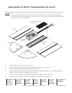
Ensure that the kit contains all the items shown in the figure below and assemble the kit components by following the
steps below.
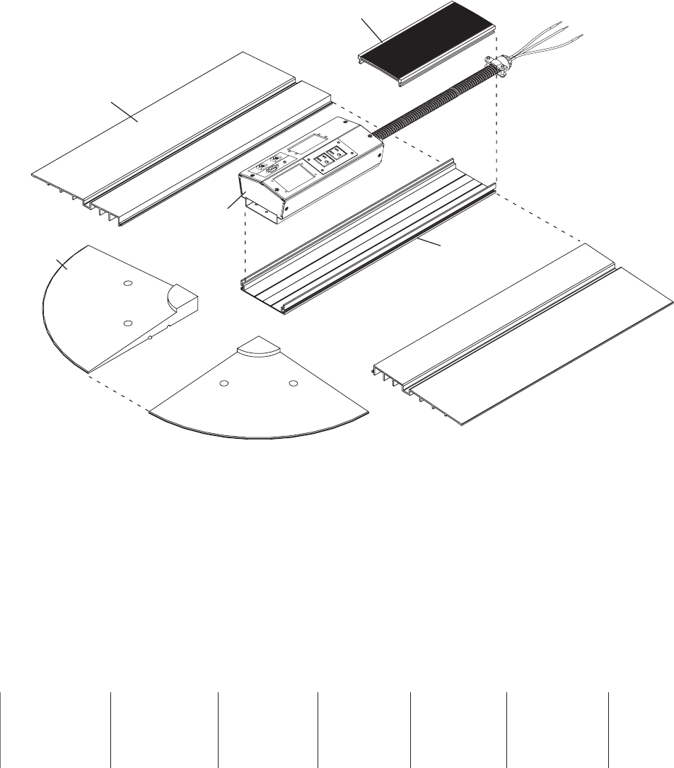
N
The illustration below shows the US version of the AVTrac Demonstration kit. The International and Universal
models are similar in size and packaging, but contain a single AC outlet, which may be connected to double insulated
power cable, or flex conduit without wires.
End Ramps
Cover Track w/ Rubber (shown)
or Carpet Finish
Side Ramps
Aluminum
Base
Track
Connectivity
(AAP) Box
1. Place aluminum base track on a firm, flat surface.
2. Attach the side ramps by mating the tabs in the ramps with the grooves in the track.
3. Place the end ramps in position at the end of the track pieces.
4. Place the connectivity box flush with the end of the track nearest the end ramps. The AC conduit should run
from the connectivity box to the opposite end of the track.
5.
Attach the cover track (either rubber or carpet finish) by snapping it onto the base track.
6. Place the pre-cut carpet pieces on top of the ramps and around the connectivity box.
w
ww.extron.com