


DTP T EU 332, DTP T EU 232, DTP T MK 332, and DTP T MK 232 • Installation and Operation 8
C
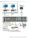
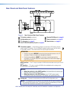
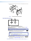
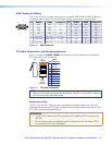
TP connector — Plug one end of a STP cable to this RJ-45 female jack
LINK SIG
OUT
on the switching transmitter. Plug the opposite end of this cable into the
DTP Input RJ-45 connector on a compatible receiver (see TP Cable
Termination and Recommendations on page 13 to properly wire the
RJ-45 connector and for detailed NOTES).
Signal LED indicator — Lights green when the transmitter outputs a video signal or a
test pattern.
Link LED indicator — Lights yellow when a device is connected and communication
is established.
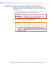
ATTENTION:
• Do not connect this connector to a computer data or telecommunications
network.
• Ne connectez pas ces port à des données informatiques ou à un réseau de
télécommunications.
D
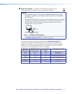
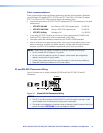
Over TP RS-232 and IR port — Plug a serial RS-232 signal, a
Tx Rx GTxRx
RS-232
OVER TP
IR
modulated IR signal (up to 40 kHz), or both into this 3.5 mm, 5-pole direct
insertion connector for bidirectional RS-232 and IR communication (see IR
and RS-232 Connector Wiring on page 14 to wire the connector).
RS-232 and IR data can be transmitted simultaneously.
E
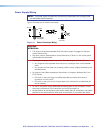
Remote RS-232 port — Plug a host device into the switching transmitter via
Tx Rx G
RS-232
REMOTE
the 3.5 mm, 3-pole direct insertion connector for remote control of the
transmitter (see IR and RS-232 Connector Wiring on page 14 to wire the
connector).
• 9600 Baud • 8 data bits
• No parity • 1 stop bit
F
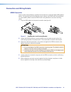
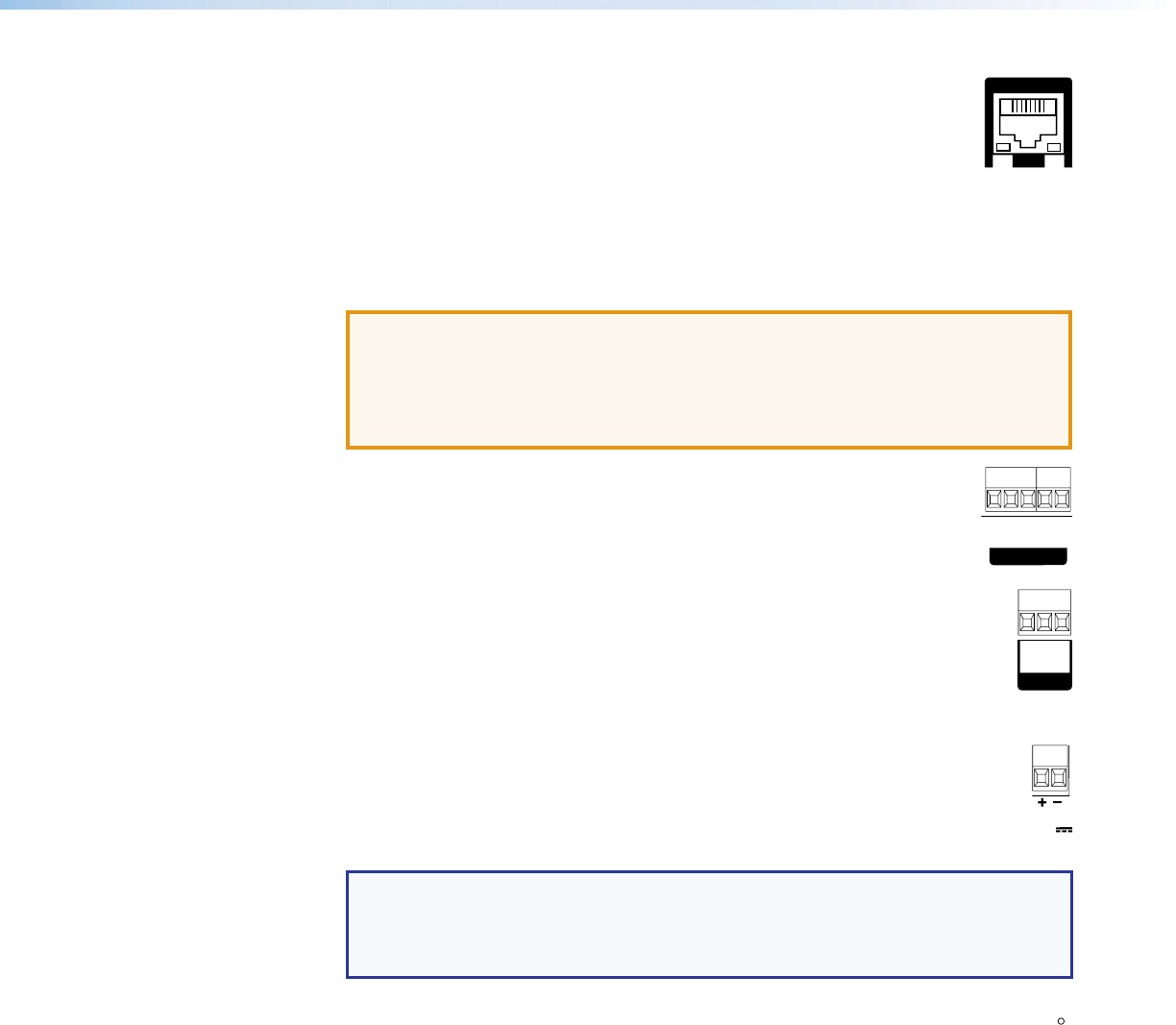
Power connector — Plug the included external 12 VDC power supply into
1.0 A
M
A
POWE
R
12V
either this 2-pole direct insertion connector (see Power Supply Wiring on page
15 to wire the connector). Or, power the receiver (see the DTP HDMI 330 User
Guide or DTP HDMI 230 User Guide, available at www.extron.com) and leave
the TP function switch in DTP position.
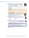
NOTE: When the TP function switch (item
A
on page 7) is in the DTP
position, one power supply can power both units.
When the TP function switch is in the HDBT position, the transmitter
and receiver each requires a local 12 VDC power supply.
G
Reset button — The Reset button initiates a reset of the switcher (see
RESET
Reset on page 17 for details).