


SW4 3G HD-SDI • Setup Guide
The Extron
®
DVI DL 101 is a dual link cable equalizer that extends DVI signals beyond the specified cable limits of
15 feet (5 m). It attaches to the end of a long cable run of up to 275 feet (84 m) for dual link and up to 200 feet (61 m)
for single link. The DVI DL supports all dual link DVI signals up to 330 MHz, including 2560x1600 or1080p at 60 Hz. It is
backwards compatible with single link, therefore supporting all single link rates up to 165 MHz, including 1920x1200 and
1080p at 60 Hz.
This guide provides basic instructions for an experienced installer to set up and operate this cable equalizer.
Installation Procedure
1. Turn off and disconnect all equipment from the
power source.
2. (Optional) If desired, mount the DVI DL on a 9.5, 6,
or 3.5 inch deep rack shelf; a projector mounting
pole; or furniture.
3. Connect a DVI source device to the DVI-Dual Link
Input DVI-I connector on the front panel.
4. Connect a DVI output device to the DVI-Dual Link
Output DVI-I connector on the rear panel.
NOTE: Dual link DVI cables must be used for
dual link DVI signals. If a single link
DVI cable is used, only single link DVI
signals are possible.
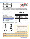
5. Wire the provided power supply as illustrated below
and connect it to the 2-pole, 3.5 mm captive screw
connector on the rear panel.
CAUTION: The power supply must not be permanently fixed
to the building structure or similar structures.
The power supply must not be located within
environmental air handling spaces or the wall
cavity.
The installation must be in accordance with the
applicable provisions of the National Electrical
Code ANSI/NFPA 70, Article 725 and the Canadian
Electrical Code, Part 1, Section 16.
The power supply must be located within the
same vicinity as the Extron A/V processing
equipment in an ordinary location, Pollution
Degree 2, secured to a podium, a desk, or an
equipment rack within a dedicated closet.
CAUTION: Applying power with incorrect voltage polarity can damage the power supply and equalizer. Identify
the negative lead by the ridges on the side of the cord. (See the illustration above.)
CAUTION: Always use a power supply by Extron for the DVI DL 101. Use of an unauthorized power supply voids all
regulatory compliance certification and may cause damage to the supply and the DVI DL.
POWER
12V
0.2A MAX
DVI DL 101
DVI-DUAL LINK OUTPUT
DVI-DUAL LINK INPUT
DVI DL 101
Power Supply
Output Cord
Captive Screw Connector
3/16” (5 mm)
MAX
SECTION A–A
Ridges
Smooth
A A
Tie
Wrap
Figure 1. Wiring the Power Connector
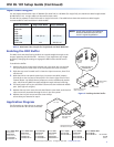
Pin
Signal
Pin Signal
Pin
Signal
1 TMDS data 2– 9 TMDS data 1– 17 TMDS data 0–
2 TMDS data 2+ 10 TMDS data 1+ 18 TMDS data 0+
3 TMDS data 11 TMDS data 1 19 TMDS data 0/5
2/4 shield shield shield
4 TMDS data 4– 12 TMDS data 3– 20 TMDS data 5–
5 TMDS data 4+ 13 TMDS data 3+ 21 TMDS data 5+
6 DDC clock 14 +5 V power 22 TMDS clock
shield
7 DDC data 15 Ground (+5 V) 23 TMDS clock+
8 CEC control* 16 Hot plug 24 TMDS clock–
detector
1
8
17
24
9
*
CEC control on pin 8 is a proprietary usage, and is not the industry
standard.
Table 1. DVI Connector Pin Assignments
1
DVI DL 101 Setup Guide