


Input cable lengths
For the highest transmission rate of 330 MHz (for dual link) or 165 MHz (for single link), the maximum cable length should
be 200 feet (61 m). Longer cables can be used at lower rates.
The DVI DL can operate in dual link mode or single link mode. The table below shows the maximum cable lengths
recommended for each resolution in both modes.
Video Resolution Single Link Mode Dual Link Mode
1280x1024
1024x768
720p
1080i
250' (76 m) 275' (84 m)
1920x1200
1600x1200
1080p
200' (61 m) 250' (76 m)
2560x1600 N/A 200' (61 m)
Enabling the DDC Buffer
The DDC clock and data lines by default are routed straight through to the
output, bypassing the DDC buffer. However, if you experience any image
problems, changing this setting to engage the DDC buffer should correct
them.
To enable the buffer:
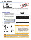
1. Remove the seven screws that hold the top cover onto the unit and the
two jack screws on either side of the front panel DVI input connector.
2. Slide the top cover forward until it clears the input connector, then lift it
off the unit.
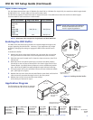
3. With the DVI DL rear panel toward you, locate the two DDC jumpers
(J5 and J4) on the two sets of three pins in the lower-right corner of the
internal board. By default these jumpers are on the middle and outside
pins, which lets the DDC lines pass straight through without buffering.
4. Lift each jumper off its pins and slide it down onto the inside and middle
pins. (See figure 2 at right.)
5. Replace the top cover onto the unit and slide the cover back until the DVI
input connector protrudes through its slot in the front panel.
6. Replace the two jack screws and the seven Philips
screws that you removed in step 1.
Application Diagram
The illustration at right shows an example
of how the DVI DL 101 can be connected.
DVI DL 101
DVI-D OUTPUT
POWER
12V
0.2A MAX
Extron
DVI DL 101
DVI Dual Link
Equalizer
15' DVI Dual
Link Cable
200' DVI Dual
Link Cable
PC
High Resolution Projector
with Dual Link Input
68-1574-50
Rev B
04 10
DVI DL 101
DVI-D OUTPUT
Jumper Pins J4 and
J5 Inside Unit
POWER
12V
0.2A MAX
DDC Buffer
Bypassed
(default)
DDC Buffer
Enabled
Jack Screw Nut
Remove screws from
sides and top (7).
Slide forward,
then up.
Extron USA - West
Headquarters
+800.633.9876
Inside USA / Canada Only
+1.714.491.1500
+1.714.491.1517
FAX
Extron USA - East
+800.633.9876
Inside USA / Canada Only
+1.919.863.1794
+1.919.863.1797 FAX
Extron Europe
+800.3987.6673
Inside Europe Only
+31.33.453.4040
+31.33.453.4050 FAX
Extron Asia
+800.7339.8766
Inside Asia Only
+65.6383.4400
+65.6383.4664 FAX
Extron Japan
+81.3.3511.7655
+81.3.3511.7656 FAX
Extron China
+400.883.1568
Inside China Only
+86.21.3760.1568
+86.21.3760.1566 FAX
Extron Middle East
+971.4.2991800
+971.4.2991880 FAX
NOTE: Avoid using couplers and adapters
between cables because this can
result in signal degradation.
©2010 Extron Electronics. All Rights Reserved - www.extron.com
Figure 2. Enabling the DDC Buffer
Table 2. Maximum Cable Lengths for Single Mode and Dual Mode DVI
2
DVI DL 101 Setup Guide (Continued)