


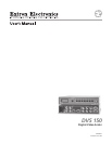
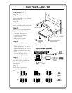

Quick Start — DVS 150
Installation
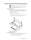
Step 1
Install the four rubber feet on the
bottom of the scaler (1A), or mount the
scaler in a rack (1B).
Step 2
Turn off power to the input and output
devices, and unplug their power cords.
Step 3
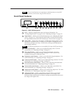
Attach the scaler to the input devices.
Input options (3) are:
Composite video (input 1)
Component video (input 2)
S-video (input 3)
RGB pass-thru (input 4)
Step 4
Attach the scaler to the output devices.
Output options (4) are:
RGsB (connected to R, G, and B)
RGBS (connected to R, G, B, and S)
RGBHV (connected to R, G, B, H,
and V)
VGA/XGA/SVGA/SXGA
(connected to RGB output connector)
Step 5
Plug the scaler, input device, and
output device into a grounded AC
source, and turn on the input and
output devices.
Step 6
Use the LCD menu screens to
configure the scaler (see the next
page).
Rubber feet
bottom side
(4 plcs)
(2) 4-40 x 1/8" screws
Use 2 mounting holes on
opposite corners
False front panel
uses 2 front holes
or
1A 1B
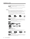
RATE
V SHIFT
H S
HIFT
CONTR
AS
T
BRIT
TINT
CO
LOR
1
2
3
D
V
S
1
0
0
DIGITAL V
IDEO SCAL
ER
4
IN
P
U
T
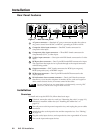
Input/Output Devices
INPUTS
R-Y
50/60 Hz
100-240 VAC .3A MAX
1
2
34
Y
B-Y
H
R
V
G
S
B
VIDEO
REMOTE
RGB
RGB
PASS-THRU
S-VIDEO
OUTPUTS
RS-232 Control
INPUT
OUTPUT
or or
CRT ProjectorLCD Projector
DLP Projector
HDTV Plasma
Laptop
Computer
DVD Player
DSS Receiver
Laserdisc Player
Composite Video
(Input 1)
RGsB RGBS RGBHV
Component Video
(Input 2)
S-video
(Input 3)
RGB Output
RGB
Pass-Thru
(Input 4)
R-Y
1
2
3
Y
B-Y
H
R
V
G
S
B
H
R
V
G
S
B
H
R
V
G
S
B
VID
R-Y
1
2
3
Y
B-Y
VID
R-Y
1
2
3
Y
B-Y
VID
3
4