


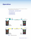
Operation
This section details the connection of fiber optic cables to the equipment for testing and
measuring the power loss of a fiber optic source.
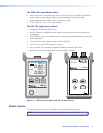
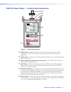
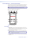
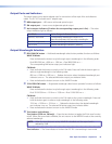
• FPM 101 Power Meter — Controls and Connections
• FLS 101 Light Source — Controls and Connections
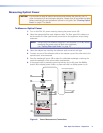
• Measuring Optical Power
• Testing Fiber Optic Links
• Testing Singlemode Links
• Using the Tone Generator
Fiber Optic Test Meters • Operation 4
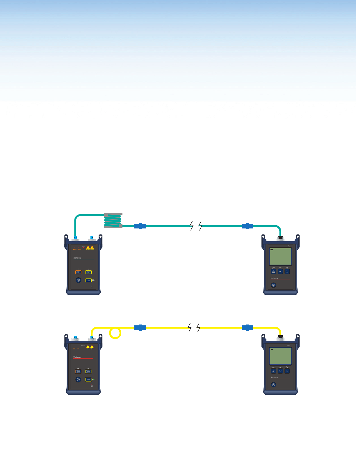
FLS 101
Fiber Optic
Light Source
Singlemode Fiber under Test
Coupler
or
Bulkhead
Mandrel
Multimode Fiber under Test
FPM 101
Fiber Optic
Power Meter
Tr
ansmit Reference
Cabl
e
Receive
Reference Cable
Tr
ansmit Reference
Cabl
e
Receive
Reference Cable
FLS 101
Fiber Optic
Light Source
FPM 101
Fiber Optic
Power Meter
Coupler
or
Bulkhead
Coupler
or
Bulkhead
Coupler
or
Bulkhead
9V
850nm1300nm 1310nm1550nm
Tone
1310nm
1550nm
850nm
1300nm
CWCW
FIBER OPTIC LIGHT SOURCE
Extron
dB
dBm
Ref
Set
Extron
Optical Power Meter
WAVE ID
9V
850nm1300nm 1310nm 1550nm
Tone
1310nm
1550nm
850nm
1300nm
CWCW
FIBER OPTIC LIGHT SOURCE
Extron
dB
dBm
Ref
Set
Extron
Optical Power Meter
WAVE ID
nm
dB
nm
dB
nm
dB
nm
dB
WAVE ID
nm
dB
nm
dB
850
3.65
1300
4.07
WAVE ID
nm
dB
nm
dB
1310
1.45
1550
1.49
FLS 101
FIBER LIGHT SOURCE
MM SM
POWER
FLS 101
FIBER LIGHT SOURCE
MM SM
POWER
POWER
FPM 101
FIBER POWER METER
POWER
FPM 101
FIBER POWER METER
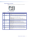
Figure 2. Typical Test Connections