


2
IN1604 Series • Setup Guide (Continued)
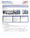
Step 3 — Connect outputs.
a. Connect a balanced or unbalanced audio output device to the 5-pole captive screw connector (
F
).
b. For the IN1604 DTP, set the HDBT/DTP switch (
H
) depending on the type of device to be connected to the TP output connector.
HDBT position — Select this position if the receiving device is an HDBaseT-compatible device. The output is HDMI with embedded
audio plus RS-232 and IR.
DTP position — Select this position if the receiving device is an Extron DTP device. The TP output is compatible with a DTP receiving
device and consists of HDMI with embedded audio, analog audio, RS-232 and IR, and remote power.
ATTENTION: Position this switch BEFORE connecting the appropriate device to the TP connector. Failure to comply can
damage the endpoint.
ATTENTION : Positionnez le sélecteur AVANT de connecter l’appareil approprié au connecteur TP. Ne pas respecter cette
procédure pourrait endommager le point de connexion.
c. For the IN1604 DTP, connect a DTP receiver or HDBaseT-compatible device to the female RJ-45 connector (
G
). For cable wiring and
recommendations, see Twisted Pair Recommendations below.
d. To pass serial or infrared data to a DTP receiver from an IN1604 DTP, connect a control device to the RS-232 and IR Over TP captive
screw connector (
I
). For wiring details, see RS-232 and IR Over DTP Wiring (IN1604 DTP Only) on page 3.
e. For the IN1604 HD, connect a digital display to the HDMI output connector (
J
).
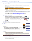
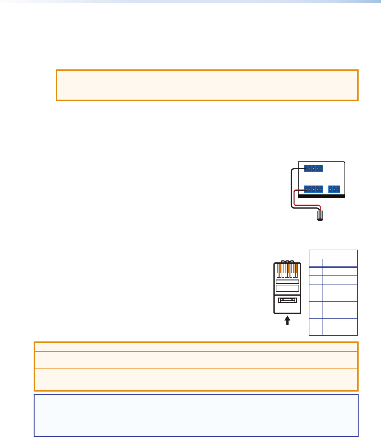
Step 4 — Connect control devices.
a. Connect contact closure devices or Extron “Show Me” cables (see the red pigtail on the “Show Me”
cable in the diagram to the right) to the Contact In 5-pole captive screw connector (see gure 1,
K
).
b. Connect tally devices or Extron “Show Me” cables (see the black pigtail on the “Show Me” cable in the
diagram to the right) to the Tally Out 5-pole captive screw connector (see gure 1,
L
).
c. For serial RS-232 control, connect a host device to the RS-232 5-pole captive screw connector on the
IN1604 DTP or the 3-pole captive screw connector on the IN1604 HD (see gure 1,
M
).
d. For control or conguration through USB, connect a host device to the front panel USB mini-B port
(see gure 2,
B
).
Step 5 — Connect power.
Connect a 100-230 VAC, 50/60 Hz power source to the AC power connector (see gure 1,
A
).
Wiring Details
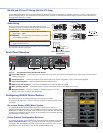
Twisted Pair Recommendations
Extron recommends using the following practices to achieve full transmission distances and reduce
transmission errors:
• Use Extron XTP DTP 24 SF/UTP cable for the best performance. At a minimum, Extron recommends
24 AWG, solid conductor, STP cable with a minimum bandwidth of 400 MHz.
• Terminate cables with shielded connectors to the TIA/EIA-T568B standard (see right).
• Limit the use of more than two pass-through points, which may include patch points, punch down
connectors, couplers, and power injectors. If these pass-through points are required, use shielded
couplers and punch down connectors.
ATTENTION:
• Do not connect these connectors to a computer or telecommunications network.
• Ne connectez pas ces ports à des données informatiques ou à un réseau de télécommunications.
• DTP remote power is intended for indoor use only. No part of the network that uses DTP remote power should be routed outdoors.
• L’alimentation DTP à distance est destiné à une utilisation en intérieur seulement. Aucune partie du réseau qui utilise l’alimentation
DTP à distance ne peut être routée en extérieur.
NOTE: When using shielded twisted pair cable in bundles or conduits, consider the following:
• Do not exceed 40% ll capacity in conduits.
• Do not comb the cable for the rst 20 meters, where cables are straightened, aligned, and secured in tight bundles.
• Loosely place cables and limit the use of tie wraps or hook-and-loop fasteners.
• Separate twisted pair cables from AC power cables.
TIA/EIA-T568B
Pin Wire Color
1 White-orange
2 Orange
3 White-green
4 Blue
5 White-blue
6 Green
7 White-brown
8 Brown
12345678
RJ-45
Connector
Insert Twisted
Pair Wires
Pins:
Pin
1
2
3
4
5
6
7
8
Wire color
White-green
Green
White-orange
Blue
White-blue
Orange
White-brown
Brown
Wire color
T568A T568B
White-orange
Orange
White-green
Blue
White-blue
Green
White-brown
Brown
TALLY OUT
CONTACT IN
Tx Rx G
3214+V
1234G
RS-232
REMOTE
Red
Black “Show Me” Cabl
e
Pigtail