


2
IN1608 Series • Setup Guide (Continued)
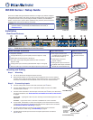
Step 3 — Connecting outputs
a. Connect a DTP receiver to the DTP output connector (see g on page 1). For cable wiring and recommendations, see Twisted Pair
Recommendations for DTP Communication below.
Signal LED — Lights green when the IN1608 is outputting active video to a DTP receiver.
Link LED — Lights amber when a valid link is established between the IN1608 and a DTP receiver.
b. To pass serial, infrared data, or other control signals, connect a control device to the RS-232 and IR Over DTP captive screw connector
(see RS-232 and IR Over DTP Wiring below).
c. Connect suitable video displays to the HDMI connectors (see h on page 1).
d. Connect analog audio output devices to the 3.5 mm 5-pole captive screw connectors (see i on page 1). For audio wiring, see Audio
Wiring below.
e. For SA and MA models, connect an audio output device to the 5 mm, 4-pole or 2-pole captive screw connector (see j on page 1).
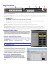
Step 4 — Connecting control devices
a. For control through Ethernet, connect a LAN or WAN to the RJ-45 connector (see k on page 1). The default IP address is
192.168.254.254. The default subnet mask is 255.255.0.0.
b. For serial RS-232 control, connect a host device to the 3-pole captive screw connector (see l on page 1). The default baud rate is 9600.
c. For control through USB, connect a host device to the front panel mini USB B port (see a of gure 2).
Step 5 — Connecting power
Connect a 100 to 240 VAC, 50-60 Hz power source to the AC power connector
(see a on page 1).
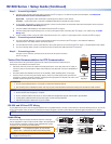
Twisted Pair Recommendations for DTP Communication
Extron recommends using the following practices to achieve full transmission distances up to
230 feet (70 m) and reduce transmission errors.
• Use Extron XTP DTP 24 SF/UTP cable for the best performance. If not using XTP DTP 24 cable, at
a minimum, Extron recommends 24 AWG, solid conductor, STP cable with a minimum bandwidth of
400 MHz.
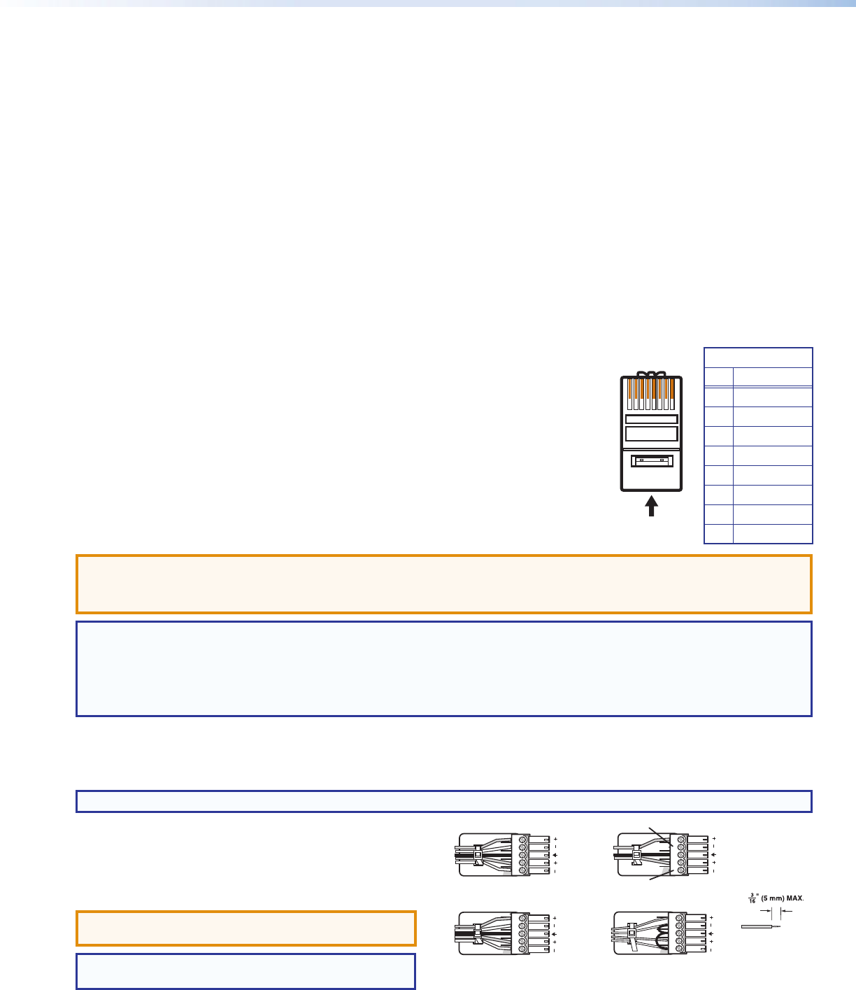
• Terminate cables with shielded connectors to the TIA/EIA T 568 B standard (shown to the right).
• Limit the use of more than two pass-through points, which may include patch points, punch down
connectors, couplers, and power injectors. If these pass-through points are required, use CAT 6 or 6a
shielded couplers and punch down connectors.
ATTENTION:
• Do not connect these devices to a computer or telecommunications network.
• DTP remote power is intended for indoor use only. No part of the network that uses DTP remote power should be routed outdoors.
NOTE: When using CAT 5e or CAT 6 cable in bundles or conduits, consider the following:
• Do not exceed 40% ll capacity in conduits.
• Do not comb the cable for the rst 20 m, where cables are straightened, aligned, and secured in tight bundles.
• Loosely place cables and limit the use of tie wraps or hook and loop fasteners.
• Separate twisted pair cables from AC power cables.
RS-232 and IR Over DTP Wiring
To pass bidirectional serial command signals between DTP-compatible devices, connect a control device to the three leftmost poles (Tx, Rx, and G)
of the 5-pole captive screw connector. To transmit and receive IR signals, connect a control device to the three rightmost poles (G, Tx, and Rx).
NOTE: RS-232 and IR data can be transmitted or received simultaneously.
Audio Wiring
Wire the audio input and output connectors as shown to the right.
Use the supplied tie-wrap to strap the audio cable to the extended tail
of the connector. This does not apply to the amplied audio output
connectors on the IN1608 SA and IN1608 MA.
ATTENTION: For unbalanced outputs, do not connect
wires to the “-” poles (see the Extron Audio Wiring Card).
NOTE: The length of exposed wires is critical. The ideal
length is 3/16 inch (5 mm).
TIA/EIA T 568 B
Pin Wire Color
1 White-orange
2 Orange
3 White-green
4 Blue
5 White-blue
6 Green
7 White-brown
8 Brown
12345678
RJ-45
Connector
Insert Twisted
Pair Wires
Pins:
Pin
1
2
3
4
5
6
7
8
Wire color
White-green
Green
White-orange
Blue
White-blue
Orange
White-brown
Brown
Wire color
T568A T568B
White-orange
Orange
White-green
Blue
White-blue
Green
White-brown
Brown
Balanced Audio Output
Tip
Ring
Tip
Ring
Sleeves
Unbalanced Audio Output
Tip
No Ground Here
No Ground Here
Tip
Sleeves
LR
LR
Unbalanced Audio InputBalanced Audio Input
Tip
Ring
Tip
Ring
Slee
ves
Tip
Sleeve
Sleeve
Tip
LR
LR
Do not tin the wires!