


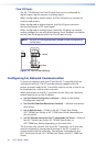

11IPL T Series • Setup
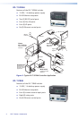
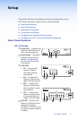
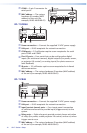
IPL T CR48
42
31
RELAY
86
75
IPL T CR48
R
42
31
INPUT
100
LINK
ACT
7
6
1
3
2
4
5
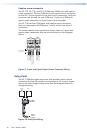
a
Power LED — A green LED lights to indicate that the unit is
receiving power.
b
Reset button — Recessed multiple function Reset button. See
Resetting the Controller for more information.
c
Input LEDs — A green LED lights to indicate that the port is active.
d
Relay LEDs — A green LED lights to indicate that the relay is
closed and activated.
e
100 LED — A green LED lights to indicate that the connection
speed is 100 Mbps. If the LED is not lit, the connection speed is
10 Mbps.
f
LINK LED — A green LED lights to indicate that the unit is
connected to an active network.
g
ACT LED — A yellow LED lights to indicate that data is being sent
or received.
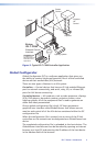
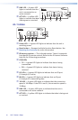
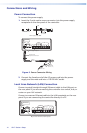
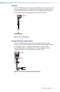
Rear Panel Features
IPL T S Series
a
Power connection — Connect
the supplied 12 VDC power
supply
b
LAN port — RJ-45 receptacle
for network connection
c
Captive screw connectors —
3.5 millimeter, 5-pole captive
screw connectors for serial
port connections
d
COM1 — 9-pin D connector for
serial port 1
e
COM2 — 9-pin D connector for
serial port 2
f
COM3 — 9-pin D connector for
serial port 3
12V
0.5A MAX
LAN
COM1
IPL T S1
1 24
MAC: 00-05-A6-XX-XX-XX
S/N:
8
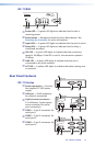
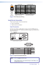
IPL T S2
2 3
1
COM1
LAN
POWER
12V
.5A MAX
COM1
TX RX TX RX
COM2
COM2
4
5
MAC: 00-05-A6-XX-XX-XX
S/N:
8
COM3
COM4
COM1
COM2
IPL T S4
2
1
LAN
POWER
12V
.5A MAX
MAC: 00-05-A6-XX-XX-XX
S/N:
8
4
5 7
6