


IRL 20 • Quick Start Guide
Step 1
Turn the equipment off and disconnect the equipment from the
power source.
Step 2
Cut a length (150'/45 m or less) of Extron Comm-Link cable to go
between the MediaLink Controller (MLC), MediaLink Switcher,
System 5 IP Switcher, or AVT 100 and the IRL 20. See appendix A for
cable part numbers.
The maximum total distance between an Extron device
(switcher, controller) and the IRL 20 is 150’ (45.7 m).
Step 3
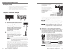
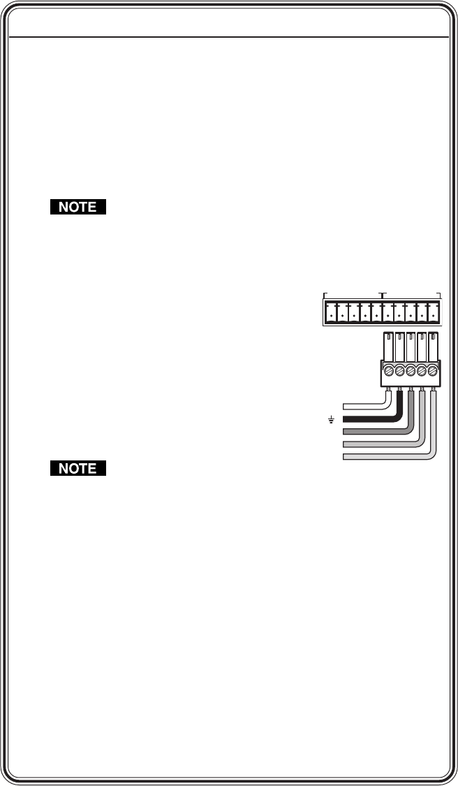
For switchers or an AVT 100, attach a 3.5 mm, 5-pole captive screw
connector to each end of the cable.
For MediaLink controllers, attach a 3.5 mm,
5-pole captive screw connector to the end of
the cable that will be plugged into the IRL 20.
Only three wires are required for most
applications, but use four wires if the IRL 20
will be daisy chained with
MediaLink Control Modules.
Refer to the device’s manual
and chapter 2 for details on
ports and pin assignments.
Do not connect
more than one IRL 20 or IR Link (either in parallel or in
series) to an Extron device. Also, read the user’s or
installation manual for each product to determine the
maximum quantity of control modules that can be used.
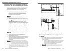
Step 4
Plug the terminated cable to one of the IRL 20’s rear panel
communications connectors.
Step 5
Plug the other end of the cable into the appropriate port of the
switcher, controller, control module, or AVT. Refer to the device’s
manual for details on ports and pin assignments. Wire both ends of
the cable identically (ground to ground, signal to signal, and so
forth).
Step 6
Attach a captive screw connector to another length of Comm-Link
cable as in step 3, then plug it into the IRL 20’s remaining
Quick Start Guide — IRL 20
QS-1
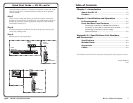
+12V
GND
CM
ModIR
SCP
+12
V
G
ND
C
M
ModIR
SCP
+12 VDC power
Modulated IR output
Control module signal
SCP control pad signal
Ground ( )