


Remote Connector
Extron • SW Switchers VGA
xi
/ MAC
xi
• User’s Guide
Page 4
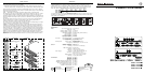
REMOTE Connector - The Remote connector provides a way to control the VGAxi / MACxi switchers
using contact closure devices such as the following:
• Extron KP-10 (wired remote keypad, IR-10 (infrared remote), RS-232 2-4-6-8 (Host computer)
• Third Party Remote Control - Information below may be used to design a third party remote control.
Remote connector pin assignments are shown in the table below (Figure 4-A). To select a different
switcher input number through the remote connector, momentarily connect the pin for the desired input
number (#) to logic ground (pin 25).
NOTE __ The duration of a momentary connection is defined as 250 — 500 milli-seconds.
The Tally pins can be used for remote indication of the switcher's selected input. Tally #1 - #6 (pins
14 -19) will indicate the switcher's selected input # with a logic low (0 volts), the Tally pins are
normally at logic high (5 volts). For example, with switcher input #2 selected, the front panel LED for
that input would be ON and Tally #2 (pin 15) would be 0 volts while the remaining Tally pins would
be 5 volts.
The schematics shown below (Figure 4-B) may be used as a guide to design and build indicator
circuits for the Tally pins. An example of an LED circuit is shown at the top, two versions of
incandescent lamp driver circuits are shown below the LED circuit.
The +5 volt source on remote connector pin 13 is limited to 100mA, if a different voltage or a higher
current is required, an external voltage source will be necessary.
Looping is a configuration technique (see Figure 4-C) that enables the total number of inputs to a
switcher (A) to be increased by connecting its highest input to the output of another switcher (B). A
Loop control signal from switcher B (Loop Out - Remote connector pin 24) to switcher A (Loop In -
Remote connector pin 12) will cause switcher A to select its highest input when an input selection
is made on switcher B. If a third switcher (C) is added, its output would connect to the highest input
on switcher B and its Loop Out signal would connect to switcher B's Loop In. An input selection on
Switcher C would cause switcher B to select its highest input and signal switcher A to select its
highest input. The selected input on switcher C would be available at Switcher A's output. An input
selection on Switcher A would drop Switchers B and C out of the loop until a selection is made on
either B or C.
Output
C
B
A
FIGURE 4-A
N/C
1N916
TALLY PIN
EXTERNAL POWER
+5V (PIN 13)
Using a Relay
& External
Power
+5V (PIN 13)
TALLY PIN
LED
330 Ohm
LED INDICATOR CIRCUIT
FIGURE 4-B
+5V (PIN 13)
EXTERNAL POWER
TALLY PIN
RESISTOR VALUE
DEPENDS ON CURRENT
REQUIREMENT OF LAM
P
330 Ohm
Using an
Opto-isolator
& External Power
INCANDESCENT LAMP CIRCUITS
RECOMMENDED RELAYS
MANUFACTURER GENERAL LOW C URRENT
AROMAT DS2 TQ
ITT/PANASONIC R-Z-5C A5W
OMRON G5Y G6H
FIGURE 4-C
Extron Electronics, Asia
41B Kreta Ayer Road
Singapore 089003
+65.226.0015 FAX +65.226.0019
Singapore
Extron Electronics, Europe
Beeldschermweg 6C
3821 AH Amersfoort
+31.33.453.4040 FAX +31.33.453.4050
The Netherlands
Extron Electronics
1230 South Lewis Street
Anaheim, CA 92805
714.491.1500 FAX 714.491.1517
USA
SM
Specifications
Refer to the safety instructions
in the literature that came with
this equipment.
Specifications
Video Input Video Signal Level _ 0 to 2 volts p-p
Video Gain _ Unity
Frequency Range (H. Sync) _ 15-145 kHz
Frequency Range (V. Sync) _ 30-170 Hz
RGB Video Bandwidth _ 350 MHz (-3 dB) (VGA
xi
and M
AC
xi
)
Input Impedance _ 75 Ohms
Output Impedance _ 75 Ohms
Termination Impedance _ 75 Ohms
Sync Input Impedance _ 510 Ohms
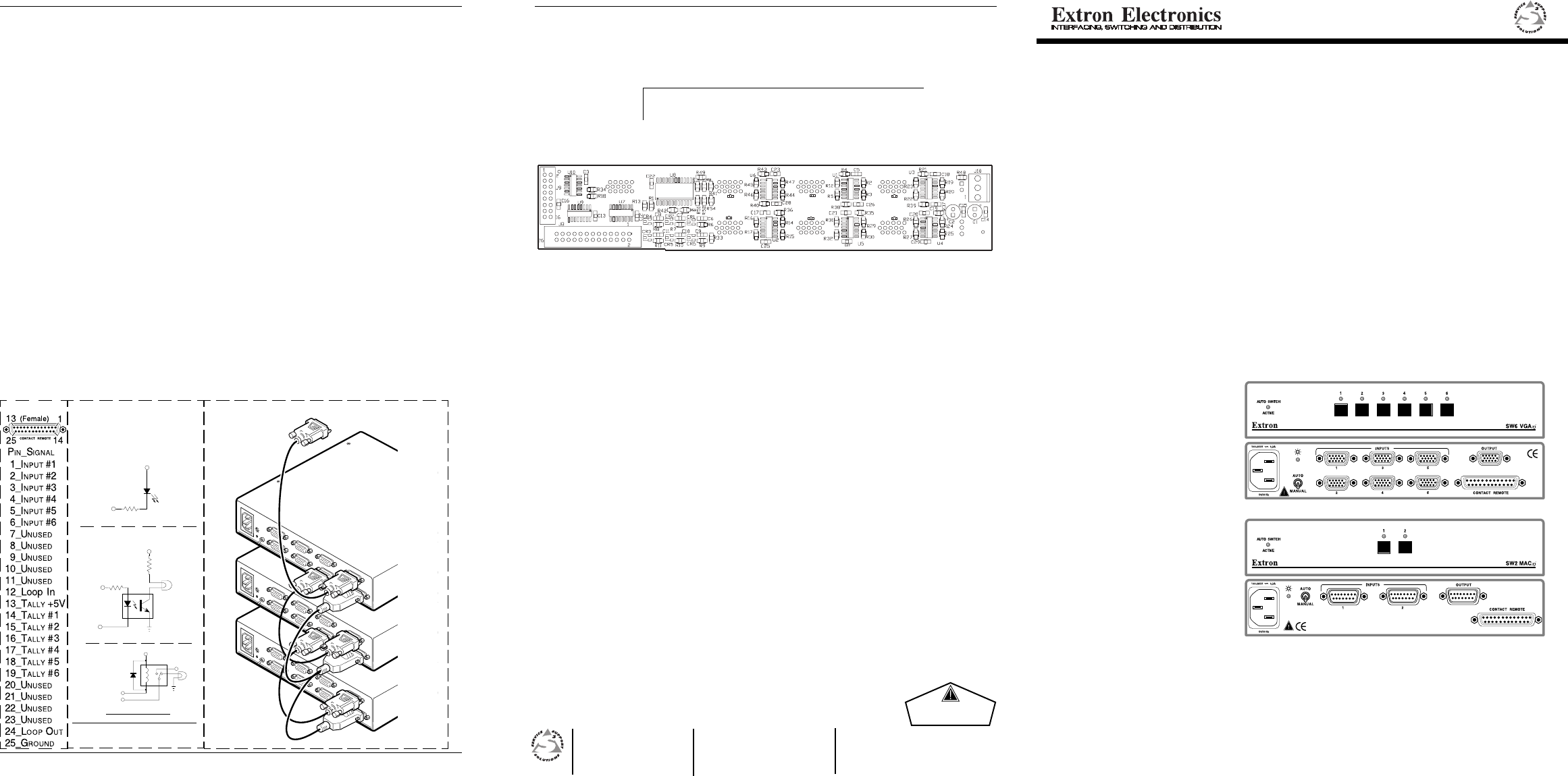
Connectors Input and Output VGA
xi __
15 pin HD D-Sub (Female)
Input and Output M
AC
xi __
15 pin D-Sub (Female)
Contact Remote _ 25 pin D-Sub
Control System Contact Closure _ Momentary (100 ms min.),
_ w/Tally feedback
Loop Signal _ Momentary low, 1 ms min, 5 ms max
General Operation Temperature _ 0°-50° C
Storage Temperature _ -40° to +70° C
Humidity _ 10% to 90% non condensing
MTBF Demonstrated _ 30,000 Hours
Vibration _ NSTA 1A in carton
Approvals _ CE, UL Listed, FCC Class A
Power Supply Internal _ 100-240 VAC 50/60 Hz, 0.2A max.
Dimensions _ 8.75" W x 9.5" D x 1.75" H
_ 22.2 cm W x 24 cm D x 4.4 cm H
Shipping Weight _ 3 lbs (1.4 kgs) - VGA
xi
and M
AC
xi
Warranty _ 2 years parts and labor
Part Numbers SW2 VGA
xi __
60-257-01
SW4 VGA
xi __
60-258-01
SW6 VGA
xi __
60-259-01
SW2 MAC
xi __
60-261-01
VGA/MAC Adapter (Composite Video) _ 26-340-01
VGA/MAC HV Adapter (MAC H/V sync) _ 26-340-02
KP-10 wired keypad remote control _ 60-111-01
IR-10 Infrared remote control _ 70-036-01
RS-232 2-4-6-8 Controller _ 60-112-01
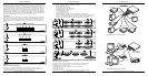
VGA connector pin-9 is normally not used and does not exist in most cases, however, some
equipment/applications may require the signal on input connector pin-9 to be passed to output
connector pin-9. If this is a requirement, it will be necessary to solder one or more jumpers onto the
inside of the rear panel. The jumpers (JMP1 - JMP6) are shown on the Printed Circuit Board layout
below. The switcher model determines which jumper applies to which input as follows:
I
NPUT 1INPUT 2INPUT 3INPUT 4INPUT 5INPUT 6
SW6 VGA
xixi
xixi
xi JMP1 JMP2 JMP3 JMP4 JMP5 JMP6
SW4 VGA
xixi
xixi
xi JMP3 JMP4 JMP5 JMP6
SW2 VGA
xixi
xixi
xi JMP5 JMP6
To access the inside of the rear panel, DISCONNECT POWER and remove four screws from the top of
the switcher. The bottom panel can then be removed. Unplug the two cables connected to the circuit
board enabling it to be removed.
JMP5
JMP3
JMP1
JMP2JMP4
JMP6
Figure 5-A
SW SWITCHERS – VGAxi
/ MACxi
SW2 VGA
xixi
xixi
xi
SW4 VGA
xixi
xixi
xi
SW6 VGA
xixi
xixi
xi
SW2 MAC
xx
xx
x
ii
ii
i
USER’S G UIDE
Written &
Printed in
the USA
89-05
68-375-01
Rev. A