


VersaTools
®
MTP DA4 and MTP DA8 • InstallationVersaTools
®
MTP DA4 and MTP DA8 • TP Cable Advantages
VersaTools
®
MTP DA4 and MTP DA8, cont’d
VersaTools
®
MTP DA4 and MTP DA8 • Connections
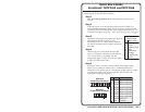
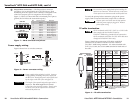
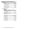
Furniture mounting
Do not attach the rubber feet. Furniture mount the DA using
the optional mounting kit (part #70-077-01) as follows:
1. Remove rubber feet if they were previously installed on
the bottom of the DA.
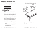
2. Attach the furniture mounting brackets to the DA with the
provided machine screws (figure 5).
M
T
P
D
A
S
E
R
I
ES
Figure 5 — Attaching the furniture mounting
brackets to an MTP DA
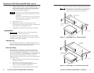
3. Hold the DA with the attached brackets against the
underside of the table or other furniture. Mark the
location of the screw holes of the bracket on the mounting
surface.
4. Drill 3/32" (2 mm) diameter pilot holes, 1/4" (6.3 mm)
deep in the mounting surface at the marked screw
locations.
5. Insert #8 wood screws into the four pilot holes. Tighten
each screw into the mounting surface until just less than
1/4" of the screw protrudes.
6. Align the mounting screws with the slots in the brackets
and place the DA against the surface, with the screws
through the bracket slots.
7. Slide the DA slightly forward or back, then tighten all four
screws to secure the unit in place.
VersaTools
®
MTP DA4 and MTP DA8 • Installation 98
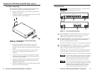
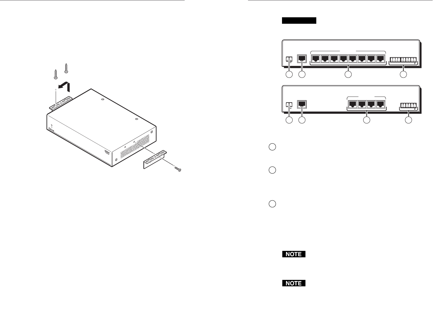
Connections
CAUTION
Do not connect these devices to a computer data or
telecommunications network.
MTP DA4
1234
1234A
OUTPUT MUTE
12V
POWER
+
-
MTP DA8
A/V INPUT
12345678
12345678A
OUTPUT MUTE
0.93A MAX
12V
POWER
+
-
A/V OUTPUTS
A/V INPUT
0.93A MAX
A/V OUTPUTS
1 2 3 4
1 2 3 4
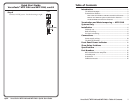
Figure 6 — DA rear panel features
1
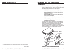
Power connector — Plug the included external 12 VDC power
supply into this 2-pole captive screw connector. See Power
supply wiring, on page 10, to wire the connector.
2
A/V Input connector — Connect one end of the cable, carrying
the video and audio or serial TP link from the transmitting
device, to this RJ-45 female connector.
See TP cable termination, on page 11, to wire the RJ-45 connectors.
3
A/V Output connector — Connect one end of a , carrying the
video and audio or serial TP link from the transmitting device,
cable to this RJ-45 female connector on the receiver.
Connect the free end of the same cable, carrying the distributed
video and audio or serial TP link, from the DA to the receiver.
See TP cable termination, on page 11, to wire the RJ-45 connectors.
The MTP DA’s output does not provide any pre-peaking
control. The total recommended distance for a complex
system with multiple DA outputs is the same as for a
simple system with a single transmitter and receiver.
See the recommended transmission ranges in the table on
page 3. The table’s recommendations apply to a complete
transmission system, which can include a single
transmitter, DA, and multiple receivers or a complex
system including multiple daisy-chained receivers.