


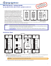
MLC 60 Decora Series • Setup Guide (Continued)
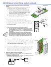
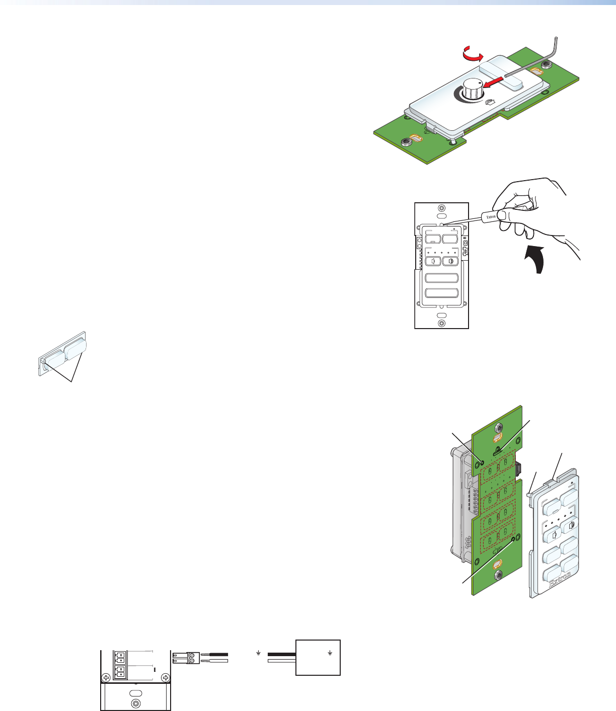
2. Change the faceplate, buttons, and volume control knob as
needed.
a. (MLC 64 RS VC D only) If changing the faceplate on the MLC 64
volume control module, first remove the volume knob:
1. Rotate the knob until the dot on the knob is aligned with
the bottom edge of the volume icon on the faceplate. The
notches in the edge of the knob and the notch in the edge of
the hole in the faceplate should be aligned, enabling you to
access the hex screw that holds the knob in place.
2. Insert the small Allen wrench (provided) into the opening.
3. Rotate the Allen wrench one-half turn counterclockwise to
loosen the hex screw, then lift off the knob.
b. Remove the faceplate from the MLC module as follows:
At the center top and bottom of the faceplate are tabs, which insert
into the slots on the MLC circuit board. Insert the flat end of a small
screwdriver into each of the holes at the top and bottom of the
faceplate and press each tab inward until the faceplate is released (see
the illustration at right).
c. If desired, replace the buttons in the faceplate as follows:
1. From the front of the faceplate, press the button membrane to be
replaced backward through its slots in the faceplate until it comes
free. If replacing the faceplate, repeat this step until all the buttons
are removed.
2. On the back of the faceplate, set the new button membrane at
the desired location, with the the two pegs in the upper-left and
lower-right corners of the membrane (shown at left) in the holes
at opposite corners of the row. Press the pegs and buttons of the
membrane into the faceplate.
d. Reattach the faceplate as follows (see the illustration at right):
Making sure that both the MLC and the board are upright, line up the tabs
at the top and bottom of the faceplate with the slots on the board, and
press the faceplate into the board until the tabs snap into place. The pegs
in the upper-left and lower-right corners of the faceplate should be seated
in the two diagonal holes on the MLC board.
e. (MLC 64 RS VC D only) If changing the volume control knob, press the new
knob onto the spindle of the volume control module, making sure that
the spindle is turned all the way to the left and that the dot on the knob
is aligned with the bottom edge of the volume icon on the faceplate.
Tighten the hex screw by rotating it one-half turn clockwise.
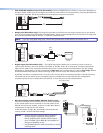
3. Connect the cables to the rear panel ports.
Attach the cables and IR emitters to the rear panel of the MLC and to the
display device or switcher as required.
z Port A RS-232 (RS models only): Connect a display device or switcher to
this serial port to be controlled via RS-232.
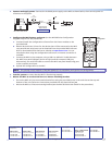
MLC RS D Rear Panel
Rx
Tx
GROUND
Tx/IR
COMMON
1
1
2
HOST/
CONFIG
PORT A
RS-232
IR/ S
DIGITAL
INPUT
Tx
PWR
12V
0.4 A MAX
RELAYS
N/O
GROUND
GROUND
GROUND
GROUND
+12 VDC
Ground ( )
Transmit (Tx)
Ground ( )
Receive (Rx)
Display Device
MUTE
LAPTOP
Pegs (2)
2
VOLUME
DISPLAY
OFF
ON
MUTE
LAPTOP
VIDEO
PC
Insert peg
on faceplate
into hole.
Peg
Insert peg
on faceplate
into hole.
Insert tab on
faceplate
into slot.
Tab
VOLUME
Extron
DISPLAY
VIDEO
PC
ON
OFF
MUTE
VOLUME
Turn Knob to
Expose Screw
Use Allen Wrench
to Loosen Screw