


Product Category
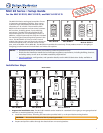
z Port B IR/S (RS models) or Port A IR (IR models): Connect a display device, switcher, or up to two IR emitters to
this port. On RS models, you can configure Port B IR/S for either serial or IR communication, using the MLC 60 Series
configuration program. On IR-only models, Port A IR supports only an IR connection.
MLC RS D Rear Panel
Rx
Tx
GROUND
Tx/IR
COMMON
1
1
2
HOST/
CONFIG
DIGITAL
INPUT
Tx
PWR
12V
0.4 A MAX
RELAYS
N/O
GROUND
GROUND
GROUND
GROUND
+12 VDC
50'
(15 m)
PORT B
IR/ S
PORT A
RS-232
Ground ( )
IR Signal
IR Emitter
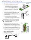
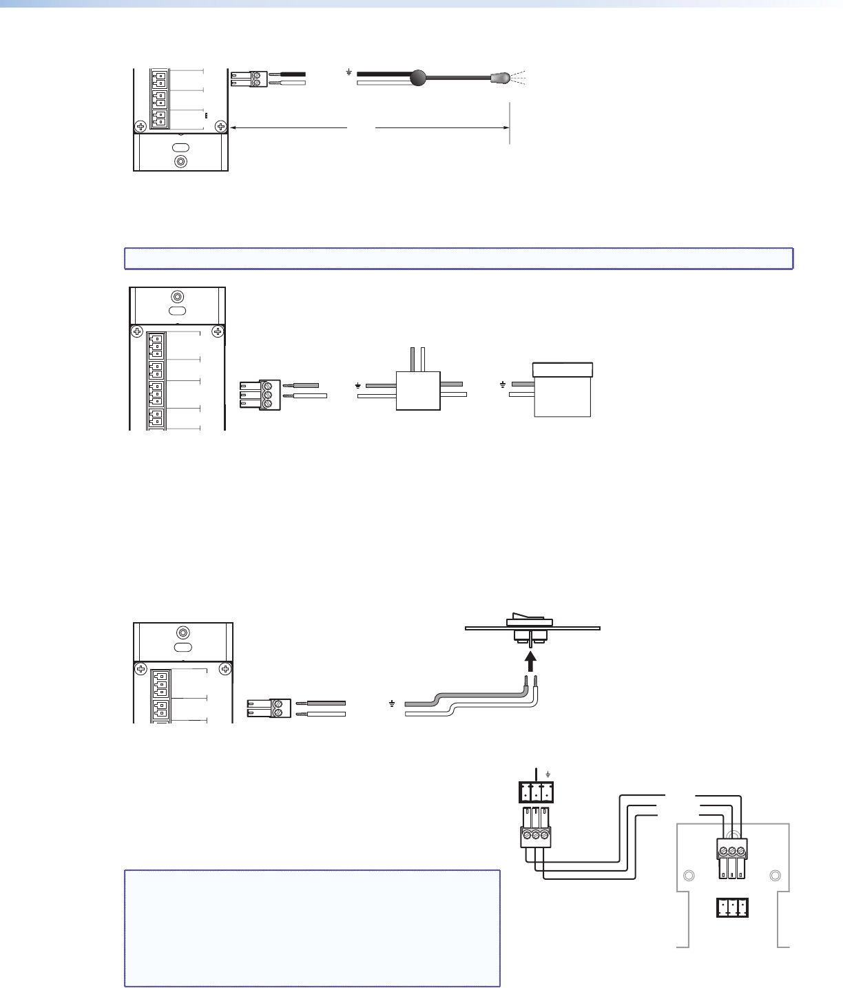
z Relays port (RS models only): The Relays port provides connections for two relays. Connect one or two devices
(such as a low-voltage controller and a motorized screen, shown in the example below) to this port. The relay ports
are normally open and rated for 24 VDC, 1 A (see the example below).
NOTE: If you are using both relay ports, connect the ground wires of both devices to common pin 3.
Ground ( )
Ground ( )
Signal 110/220 V
Rx
Tx
GROUND
Tx/IR
COMMON
1
1
2
HOST/
CONFIG
RS-232
DIGITAL
INPUT
Tx
PWR
12V
0.2 A MA
X
RELAYS
N/O
GROUND
GROUND
GROUND
GROUND
+12 VDC
MLC 62 RS D
Rear Panel
Low Voltage
Screen Control
Motorized
Screen
Power
Supply
1
2
3
Pin:
MLC RS D Rear Panel
PORT B
IR/ S
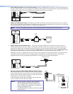
z Digital Input port (RS models only) — The Digital Input port enables you to connect a switch or sensor to
control other devices in the room that are connected to the MLC serial, IR, or relay ports. The port measures the
high and low states of the connection between the switch or sensor and the connected device. For the voltage
thresholds, a voltage below 1.0 VDC is measured as logic low, and a voltage above 1.5 VDC as logic high. When a
threshold between the states is crossed (from high to low and vice versa), the selected action occurs.
By default, this port is configured with a 5 V pull-up for use with basic non-powered switches. If the device being
connected has its own power source, configure the port to disable the pull-up mode (see the configuration
program help file for port configuration procedures). To wire this port, see the example below.
Ground ( )
Digital Input
Rx
Tx
GROUND
Tx/IR
COMMON
1
1
2
HOST/
CONFIG
RS-232
IR/ S
DIGITAL
INPUT
Tx
PWR
12V
0.2 A MAX
RELAYS
N/O
GROUND
GROUND
GROUND
GROUND
+12 VDC
MLC RS D Rear
Panel
Two-position Switch
1
2
Pin:
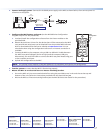
z Wire the volume control module (MLC 64 RS VC D only) —
Connect the remote volume control port of an Extron amplifier
to the 3-pole captive screw connector on the rear panel of the
MLC 64 volume control module, as shown at right. No software
configuration is required for this module.
In the illustration at right, A = ground, B = Volume and mute
control, and C = 10 VDC reference voltage.
NOTES: • Choose an Extron amplifier that is capable of
remote volume control and muting. Not all
Extron amplifiers have remote volume control
ports. The MPA 122 or MPA 401 are examples of
the type of amplifier to use.
• Use shielded cable for audio connections to avoid
inducing noise.
3
Amplifier
Rear Panel
MLC 64 VCM
Rear Panel
10V
Vol/Mute
123
A B C
10 V
Vol/Mute
Ground
GND
VOL
10V