


68-2166-50 Rev. A
11 11
Extron USA - West
Headquarters
+800.633.9876
Inside USA/Canada Only
+1.714.491.1500
+1.714.491.1517 FAX
Extron USA - East
+800.633.9876
Inside USA/Canada Only
+1.919.863.1794
+1.919.863.1797 FAX
Extron Europe
+800.3987.6673
Inside Europe Only
+31.33.453.4040
+31.33.453.4050 FAX
Extron Asia
+800.7339.8766
Inside Asia Only
+65.6383.4400
+65.6383.4664 FAX
Extron Japan
+81.3.3511.7655
+81.3.3511.7656 FAX
Extron China
Sales: + 4000.EXTRON
+4000.398.766
Inside China Only
+86.21.3760.1568
+86.21.3760.1566 FAX
Extron Middle East
+971.4.2991800
+971.4.2991880 FAX
© 2011 Extron Electronics All rights reserved. www.extron.com
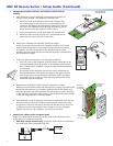
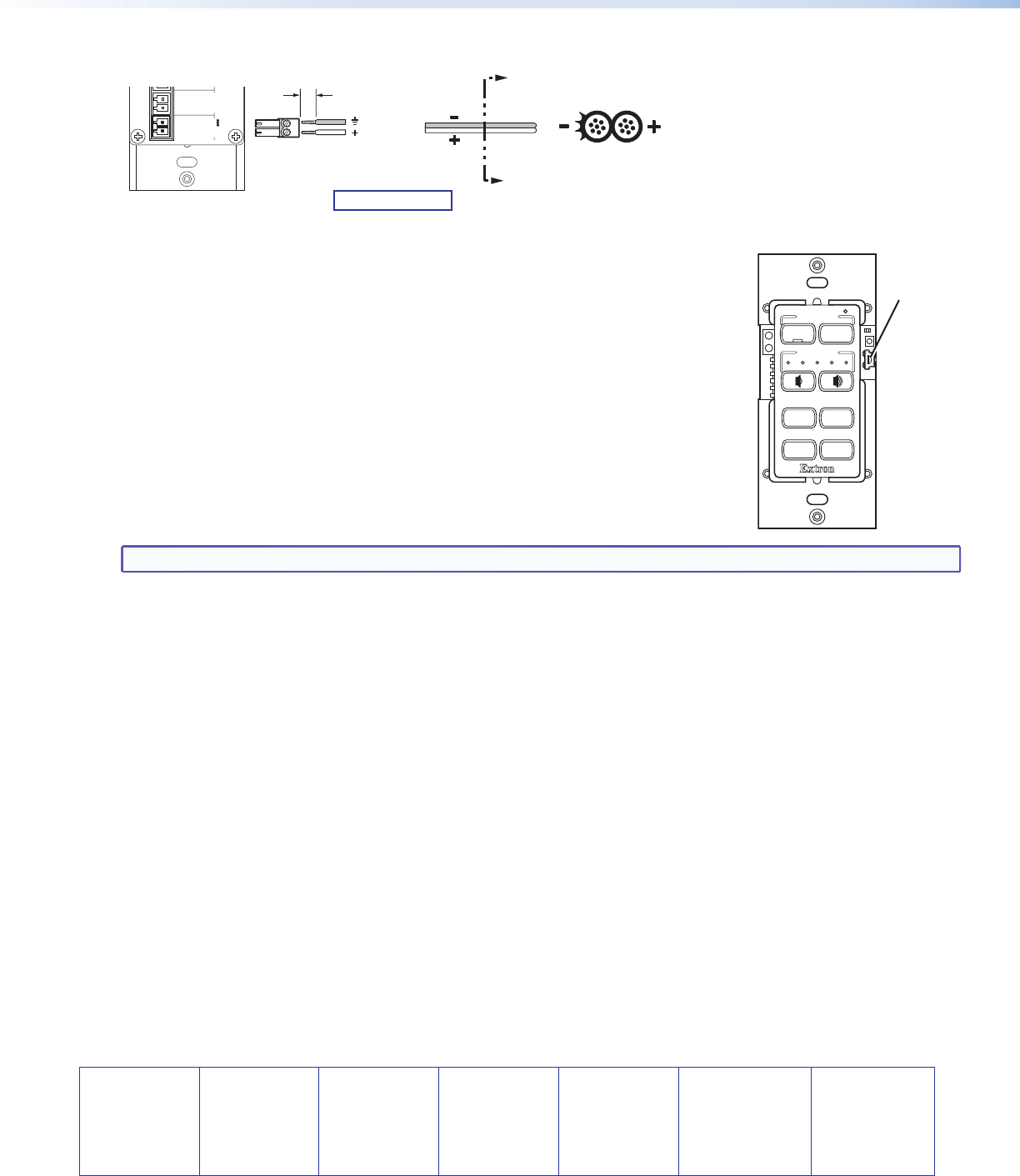
4. Connect and apply power. Connect the included power supply to the MLC as shown below, then connect power to
all devices in the system.
SECTION A–A
A
A
Power Supply
Output Cord
Ridges
Smooth
3/16”
(5 mm) Max.
MLC RS D Rear Panel
Rx
Tx
GROUND
Tx/IR
COMMON
1
1
2
HOST/
CONFIG
PORT A
RS-232
IR/ S
DIGITAL
INPUT
Tx
PWR
12V
0.4 A MAX
RELAYS
N/O
GROUND
GROUND
GROUND
GROUND
+12 VDC
Ground
12 VDC input
Ground all devices.
5. Configure the MLC buttons and ports (see the MLC 60 Series Configuration
Program Help File for the procedures):
a. Load and install the configuration software from the Extron website or the
provided DVD.
b. Obtain device drivers. Drivers for the devices that will be connected to the MLC
rear panel IR and serial ports can be obtained from the provided MLC software
DVD or downloaded from the Extron website at www.extron.com. You can
also obtain them using the configuration software if an Internet connection is
available.
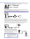
c. Connect the MLC to the computer, using a USB A to USB mini B cable between
the MLC front panel USB port (shown at right) and the computer USB port.
Alternatively, use an RS-232 cable to connect the MLC rear panel Host/Config port
to the computer serial port.
d. Upload the configuration to the MLC.
NOTE: The volume control module of the MLC 64 RS VC D is standalone and requires no configuration.
6. Test the system to ensure that the MLC is functioning properly.
7. Mount the MLC to an electrical box or a Decora mounting bracket.
z Secure the MLC unit into a mounted electrical box using the provided screws in the oval slots at the top and
bottom of the unit (follow the instructions provided with the electrical box); or
z Mount the MLC to a Decora mounting bracket (see the MLC 60 Series User Guide for the procedure).
4
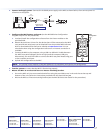
VOLUME
DISPLAY
Extron
PC
VIDEO
LAPTOP
MUTE
ON
OFF
USB
Configuration
Port