


MLM 104 Faceplates Installation Guide, cont’d
MLM 104 Faceplates • Installation Guide4
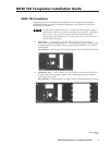
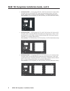
4. Align the openings in the new MLM faceplate with the controller’s buttons,
knob, and LEDs, then place the new faceplate on the MLC 104 IP Plus.
5. Replace the four screws removed in step 2, and hand tighten them.
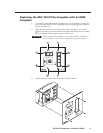
6. Install the MLC 104 IP Plus controller in a wall or furniture as appropriate.
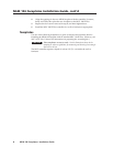
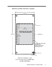
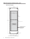
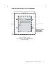
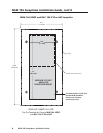
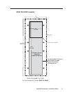
Templates
Use one of the following templates as a guide to measure and mark the hole for
installing the MLM 104 faceplate with an attached MLC 104 IP Plus. (Refer to your
MLC 104 IP User’s Manual for instructions on preparing the mounting site.)
CAUTION
These templates are not to scale. Use the dimensions shown in the
templates as reference guidelines for measuring and drawing the rectangle
that will be cut out.
The MLC controller requires a depth of at least 2.0" (5.1 cm) inside the wall or
furniture.