


2-5MediaLink Switchers • Installation
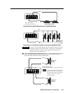
Do not connect RS-232 control devices to the MLC/IR 5-pole captive screw
connector and to the 9-pin RS-232/Contact Closure port simultaneously. A
conflict may occur.
Connect devices to both ports at the same time only if
• the 9-pin connector is used for contact closure and
• the MLC/IR port is used for RS-232.
9
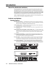
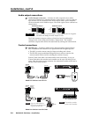
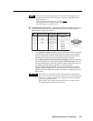
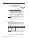
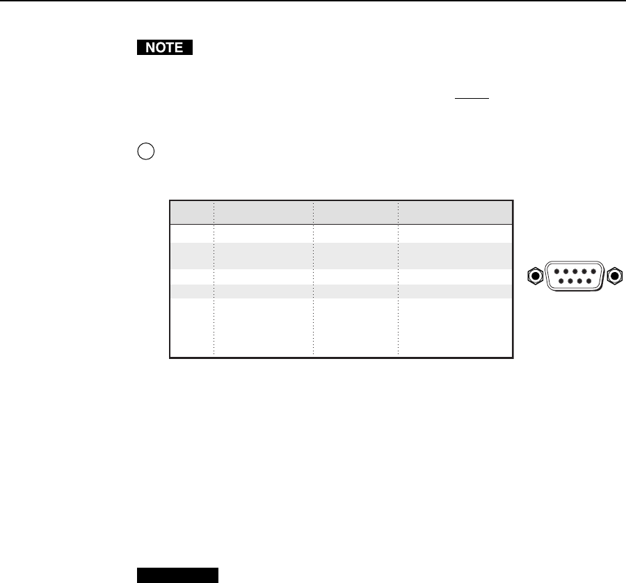
RS-232/Contact Closure port — This port can function as an RS-232 port or as
a contact closure port. Do not connect RS-232 devices to both this and the
MLC/IR port. See the above note.
Pin
RS-232
function
Description
Contact closure
1 – Input 1 Input 1
2 Tx Transmit data –
3 Rx Receive data –
4 – Input 2 Input 2
5 Gnd Signal ground –
6 – Input 3 Input 3
7 – Input 4 Input 4
8 – Input 5 Input 5
9– Input 6 Input 6
DB9 Pin Locations
Female
51
96
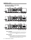
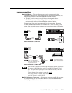
• For a stand-alone MLS switcher, connect a cable from the host computer
or a third party control system to this 9-pin D connector to set up and
remotely control the switcher. Alternatively, connect a contact closure
keypad to this connector for remote control of input selection.
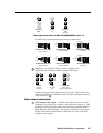
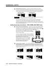
• For an MLS switcher slaved to an MLC controller, connect a cable from
the MLC’s MLS/Power port to the switcher’s MLC/IR connector (not to
this 9-pin RS-232 port). Once the system has been cabled and set up via
the Windows-based software, the MLC or a host computer
communicating through the MLC can be used to remotely control the
switcher. Refer to chapter four of the MLC 206 User’s Manual and the
MediaLink Control Program help file for details on configuring an MLC-
MLS system.
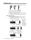
CAUTION
If the switcher is connected to an MLC 206 controller via the MLC/IR
port, do not connect an RS-232 device to the MLS’s 9-pin RS-232/Contact
Closure port. Conflicts between RS-232 signals received from both ports
could cause system disruptions.
When an MLC 206 is connected to the MLC/IR port, a contact closure
device may be attached to the 9-pin connector.