


www.extron.com
© 2008 Extron Electronics. All rights reserved.
Pricing and specifications may change without notice.
USA West
+1.714.491.1500 / +800.633.9876
+1.714.491.1517 FAX
USA East
+1.919.863.1794 / +800.633.9876
+1.919.863.1797 FAX
China
+86.21.3760.1568 / +400.883.1568
+86.21.3760.1566 FAX
Japan
+81.3.3511.7655
+81.3.3511.7656 FAX
Europe
+31.33.453.4040 / +800.3987.6673
+31.33.453.4050 FAX
Dubai
+971.4.2991800
+971.4.2991880 FAX
Asia
+65.6383.4400 / +800.7339.8766
+65.6383.4664 FAX
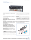
MMX AV Series
a/V Matrix SwitcherS
Audio outPut
Number / Signal type
Captive screw models ............ 2 stereo, balanced/unbalanced
RCA connector models ........... 2 stereo, unbalanced
Connectors
Captive screw models ............ (2) 3.5 mm captive screw connectors, 5 pole
RCA connector models ........... 2 pairs of female RCA connectors
Impedance ........................ 50 ohms unbalanced, 100 ohms balanced
Gain error ......................... ±0.1 dB channel to channel
Maximum level (Hi-Z) ........... >+21 dBu, balanced or unbalanced at 1%THD+N
Maximum level (600 ohm) ..... >+15 dBm, balanced or unbalanced at 1%THD+N
control / reMote
—
Switcher
Serial control port ............... RS-232, female 3.5 mm captive screw connector, 3 pole
Baud rate and protocol ......... 9600 baud, 8 data bits, 1 stop bit, no parity
Serial control
pin configurations ............... 1 = TX, 2 = RX, 3 = GND
Program control ................. Extron’s control/configuration program for Windows
®
Extron’s Simple Instruction Set (SIS
™
)
GenerAl
External power supply ......... 100 VAC to 240 VAC, 50/60 Hz, external, universal;
to 12 VDC, 1 A, regulated
Power input requirements ..... 12 VDC, 0.5 A
Temperature / Humidity ........ Storage: -40 to +158 °F (-40 to +70 °C) / 10% to 90%, noncondensing
Operating: +32 to +122 °F (0 to +50 °C) / 10% to 90%, noncondensing
Rack mount ...................... Yes, with optional 1U rack shelf, part #60-190-01 or 60-604-01; or
VersaTools
®
rack shelf, part #60-190-20 or 60-604-20
Enclosure type ................... Metal
Enclosure dimensions .......... 1.75" H x 8.75" W x 3.0" D (1U high, half rack wide)
4.4 cm H x 22.2 cm W x 7.6 cm D (Depth excludes connectors.)
Product weight .................. 4.0 lbs (1.8 kg)
Shipping weight ................. 5 lbs (3 kg)
Vibration .......................... ISTA 1A in carton (International Safe Transit Association)
Listings ............................ UL, CUL
Compliances ..................... CE, FCC Class A , VCCI, AS/NZS, ICES
MTBF .............................. 30,000 hours
Warranty .......................... 3 years parts and labor
NOTE: All nominal levels are at ±10%. Specifications are subject to change without notice.
SPecificAtionS
Video
Routing
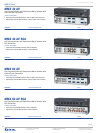
MMX 42 Series .................... 4 x 2 matrix
MMX 62 Series .................... 6 x 2 matrix
Gain ................................ Unity
Bandwidth ........................ 150 MHz (-3 dB), fully loaded
0 - 10 MHz: no more than 0.1 dB to -0.1 dB
0 - 30 MHz: no more than 0.5 dB to -0.5 dB
Phase between I/Os ............ <1.28º at 3.58 MHz
Differential phase error ........ 0.1º at 3.58 MHz and 4.43 MHz
Differential gain error .......... 0.1% at 3.58 MHz and 4.43 MHz
Max. propagation of delay ..... 5 ns typical (±1 ns)
Crosstalk .......................... -50 dB @ 5 MHz
Switching speed ................. 200 ns (max.)
Video inPut
Number / Signal type ........... 4 or 6 composite video
Connectors ....................... 4 or 6 female BNC
Nominal level .................... 1 Vp-p
Minimum / Maximum levels ... Analog: 0.5 V to 2.0 Vp-p with no offset
Impedance ........................ 75 ohms
Return loss ....................... <-30 dB @ 5 MHz
DC offset (max. allowable) ....... 1.5 V
Video outPut
Number / Signal type ........... 2 composite video
Connectors ....................... 2 female BNC
Nominal level .................... 1 Vp-p
Minimum / Maximum levels ... 0 V to 2.0 Vp-p
Impedance ........................ 75 ohms
Return loss ....................... -30 dB @ 5 MHz
DC offset .......................... ±5 mV maximum with input at 0 offset
Switching type ................... Vertical interval
Sync
Standards ......................... NTSC 3.58, NTSC 4.43, PAL, SECAM
Audio
Routing
MMX 42 Series .................... 4 x 2 stereo matrix
MMX 62 Series .................... 6 x 2 stereo matrix
Gain
Captive screw models ............ Unbalanced output: -6 dB; balanced output: 0 dB
RCA connector models ........... Unbalanced output: 0 dB
Frequency response ............ 20 Hz to 20 kHz, ±0.05 dB
THD + Noise ...................... 0.03% @ 1 kHz at rated nominal level
S/N ................................. >90 dB, output 21 dBu, balanced, at maximum output (unweighted)
Crosstalk .......................... <-80 dB @ 1 kHz, fully loaded
Stereo channel separation .... >90 dB @ 1 kHz
CMRR .............................. >75 dB @ 20 Hz to 20 kHz
Audio inPut
Number / Signal type
Captive screw models ............ 4 or 6 stereo, balanced/unbalanced
RCA connector models ........... 4 or 6 stereo, unbalanced
Connectors
Captive screw models ............ (4 or 6) 3.5 mm captive screw connectors, 5 pole
RCA connector models ........... 4 or 6 pairs of female RCA connectors
Impedance ........................ >10k ohms unbalanced/balanced, DC coupled
Nominal level .................... -10 dBV (316 mV)
Maximum level .................. +19.5 dBu, (balanced or unbalanced) at 1%THD+N
Input gain adjustment .......... –18 dB to +24 dB, adjustable per input via RS-232 only
NOTE: 0 dBu = 0.775 Vrms, 0 dBV = 1 Vrms, 0 dBV ≈ 2 dBu
MMX AV Series Accessories
oPtionAl AcceSSorieS Model deScriPtion PAGe PArt #
IPL T S2 Two Serial Port IP Link
®
Ethernet Control Interface . . . . . . . . . . . . . . . . . . . . . . . . . . . . . . . . page 474 60-544-81
291