


MMX 42/62 Series Matrix Switchers • Operation
Operation
MMX 42/62 Series Matrix Switchers • Operation
3-33-2
Front Panel Controls and Indicators
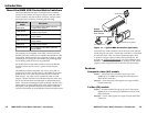
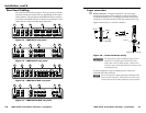
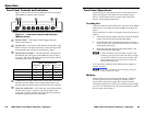
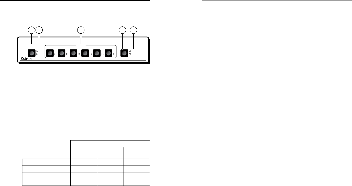
Figure 3-1 shows the controls and indicators on the front panel
of the MMX 62 compact matrix switcher.
CONFIGOUTPUTS
1
2
42 31 5 6
INPUTS
MMX SERIES
AUDIO
VIDEO
1
4
5
2
3
Figure 3-1 — Front panel controls and indicators
(MMX 62 shown)
a
Outputs button — The Outputs button toggles between
output 1 and output 2.
b
Output LEDs — The Output LEDs indicate the selected output.
When an output is muted (audio and/or video) the input LED
for the muted output will be off (audio and/or video).
c
Input buttons and LEDs — The input buttons (1 through 4 on
the MMX 42 and 1 through 6 on the MMX 62) select an input
for output. The input LEDs indicate the selected input and the
video and audio mutes as follows:
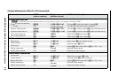
Input LED indications
Video only
tie
Audio only
tie
Video and
audio tie
Input selected
Lit Blinking Lit
Audio muted
Lit Off Lit
Video muted
Off Blinking Blinking
Video and audio muted
Off Off Off
d
Configuration (Config) button (video and/or audio selection) —
When pressed and released, the Configuration button cycles
through video and audio, audio only, and video only selection.
e
Video and Audio LEDs — The Video and Audio LEDs indicate
whether video, audio, or both are selected for display and/
or selection. If audio is broken away and video and audio are
selected for display, the Audio LED blinks.
Front Panel Operations
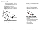
Plug in all system components and turn on the input devices
(such as DVD players and DSS receivers) and the output
devices. Set the input devices to output video using each
device’s own operating instructions.
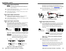
Creating ties
A Tie is an input-to-output connection. An input can be tied to
both outputs. (An output can never be tied to more than one
input.)
Create video and/or audio ties using the front panel buttons as
follows:
1. Press and release the Outputs button to select the desired
output. The LED for the selected output lights.
2. Press and release the Configuration button as necessary
to select either video and audio (audio follow) or video or
audio (audio breakaway).
3. Press and release the button for the desired input. The
LED for the selected input lights.
N
If audio and video are tied from different inputs (audio
breakaway), and if you select video and audio for display,
the Video LED and the LED for the selected video input
light steadily and the Audio LED and the LED for the
selected audio input blink .
A tie can also be created by an RS-232 device (see chapter 4,
"Remote Control").
N
If an output is muted via RS-232, pressing any input
button unmutes the output.
Memory
Audio settings are saved in nonvolatile memory. When the
switcher is powered off, the settings are retained. When
the switcher is powered on again, the switcher recalls the
connections made prior to power down and the saved settings
are active. On initial power on, the switcher defaults to input 1
tied to output 1 and output 2.