


VersaTools
®
MSW 4V & 4SV • Installation and Connections
VersaTools
®
MSW 4V & 4SV • Installation
VersaTools
®
MSW 4V & 4SV, cont’d
5
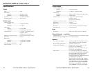
Contact connector — Connect a remote contact
closure device to the switcher for remote control of
the switcher, or daisy chain the switcher to other
MSWs for remote control of the other switchers,
via this 5-pin captive screw connector.
The switcher must be in normal (manual) switch mode
for contact closure to work. See Mode selection, on
page 9.
To select an input using a contact closure device, such as an
Extron CCR 204 contact closure remote control (part #60-794-02)
or a locally constructed device, momentarily short the pin for
the desired input number to logic ground (pin 5). To force one
of the inputs to be always selected, leave the short in place. The
short overrides any front panel input selections.
You can also daisy chain multiple MSWs via the Contact
connector for front panel control of all switchers; touch the
input button on one MSW to switch all MSWs. Wire pin 1 to
pin 1, pin 2 to pin 2, and so on.
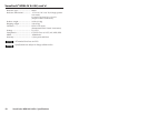
6
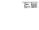
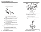
Power connector — Plug the external 12 VDC power supply
into this 2-pole captive screw connector. The power supply is
included with the unit. Figure 8 shows how to wire the
connector.
Power Supply
Output Cord
Captive Screw
Connector
0.2” (5 mm)
SECTION A–A
Ridges
Smooth
AA
Figure 8 — Power connector wiring
CAUTION
Power supply voltage polarity is critical. Incorrect
voltage polarity can damage the power supply and
the MSW. Identify the power cord negative lead by
the ridges on the side of the cord (figure 8).
CAUTION
The length of the exposed (stripped) copper wires is
important. The ideal length is 0.2" (5 mm).
Longer bare wires can short together. Shorter wires
are not as secure in the captive screw connectors
and could be pulled out.
Vertical interval switching
The MSWs switch inputs during the vertical interval of the
video signal that is input on input 1. In a genlocked system,
switching to any input is glitch-free if one of the genlocked
devices is connected to input 1.
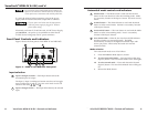
Rear panel connections
The MSW switches on the vertical interval of input 1.
For seamless switching, ensure one of the genlocked
devices is connected to input 1.
MSW 4V
MSW 4SV
MSW 4SV
POWER
12V
.5A MAX
INPUTS
OUTPUTS
CONTACT
1
2
3
4
1
2
3
4
A
B
MSW 4V
POWER
12V
.5A MAX
INPUTS
OUTPUTS
CONTACT
1
2
3
4
A
B
1
2
3
4
4
4
6 5
2
36 5
1
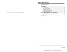
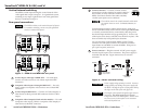
Figure 7 — MSW 4V and MSW 4SV rear panel
1
S-video Inputs 1 through 4 (MSW 4SV) — For each input,
connect an S-video source to one of these 4-pin mini DIN
connectors.
2
Composite video Inputs 1 through 4 (MSW 4V) — For each
input, connect a composite video source to one of these BNC
connectors.
3
S-video Output (MSW 4SV) — Connect an S-video display or
other device to this 4-pin mini DIN connector for the S-video
output.
4
Composite video Output(s) (both switcher models) — For each
composite video output, connect a composite video display or
other device to this BNC connector.
VersaTools
®
MSW 4V & 4SV • Connections 76 VersaTools
®
MSW 4V & 4SV • Connections
CONTACT
1
2
3
4